Inertial mass guided single axis vibration test machine

Active Publication Date: 2007-03-22
TEAM
View PDF10 Cites 6 Cited by
  • Summary
  • Abstract
  • Description
  • Claims
  • Application Information

AI Technical Summary

Benefits of technology

[0009] One embodiment of the present invention comprises a single axis vibration test system comprising a vibration force generator which includes a test object support base. The “support base” is commonly called a “head expander” in a vibration testing application. The head expander increases the surface area available for mounting the item to be tested. The force generator induces single axis motion in a test object affixed to the support base.
[0011] Cooperating coupling devices support the vibration force generator for single axis vibration while resisting cross-axis motion. The coupling devices are rigidly connected to the reaction mass. A rigid sub-structure supports resilient support bearings or isolators, which in turn support the reaction mass (or masses). The supporting sub-structure is affixed to ground. The resilient support bearings between the reaction mass and the supporting sub-structure provide a “disconnect” that avoids any rigid mechanical connection between the reaction masses and ground.
[0014] The present invention avoids a mechanical connection between the head expander guidance components and the reaction mass that would normally have undesired flexibility characteristics (resonances) within the test frequency range.

Problems solved by technology

Single axis vibration test machines in the past have experienced certain undesired levels of cross-axis motion, which in turn produce inaccurate test results.
Conventional single axis shakers have not avoided the unwanted effects of cross-axis vibration.
Conventional vertical axis vibration systems have been known to generate undesired cross-axis motions when the inherent mechanical resonances of the system are excited by the vibration applied to the vertical axis.
Commercially available shakers by themselves are often incapable of supporting and guiding large and / or heavy test items.
The weight of many test items may exceed the allowable weight specified by the shaker manufacturer, and the center of gravity location may produce moment loads that exceed the allowable load on the shaker.

Method used


Image

  • Inertial mass guided single axis vibration test machine
  • Inertial mass guided single axis vibration test machine
  • Inertial mass guided single axis vibration test machine

Examples


Embodiment Construction

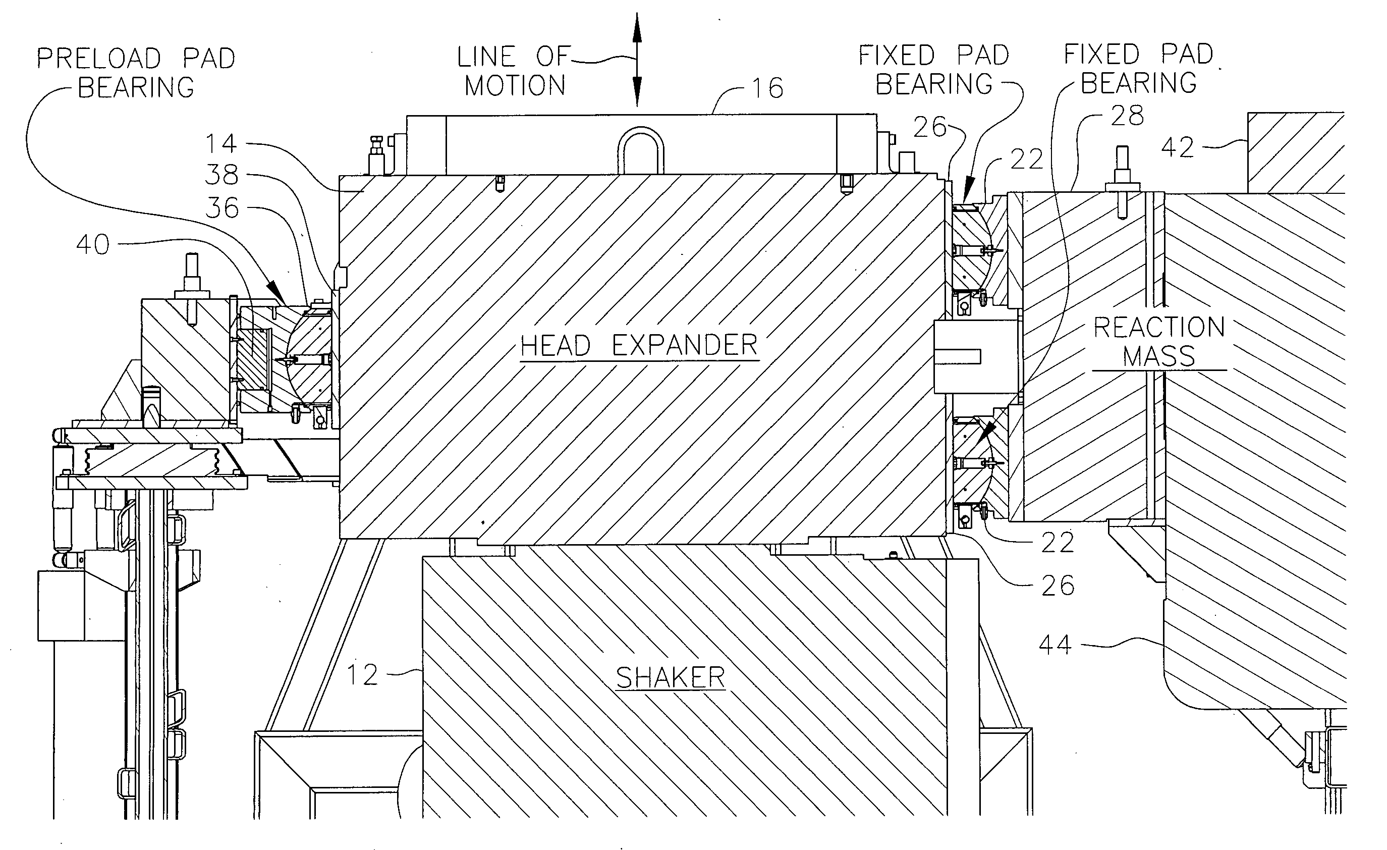
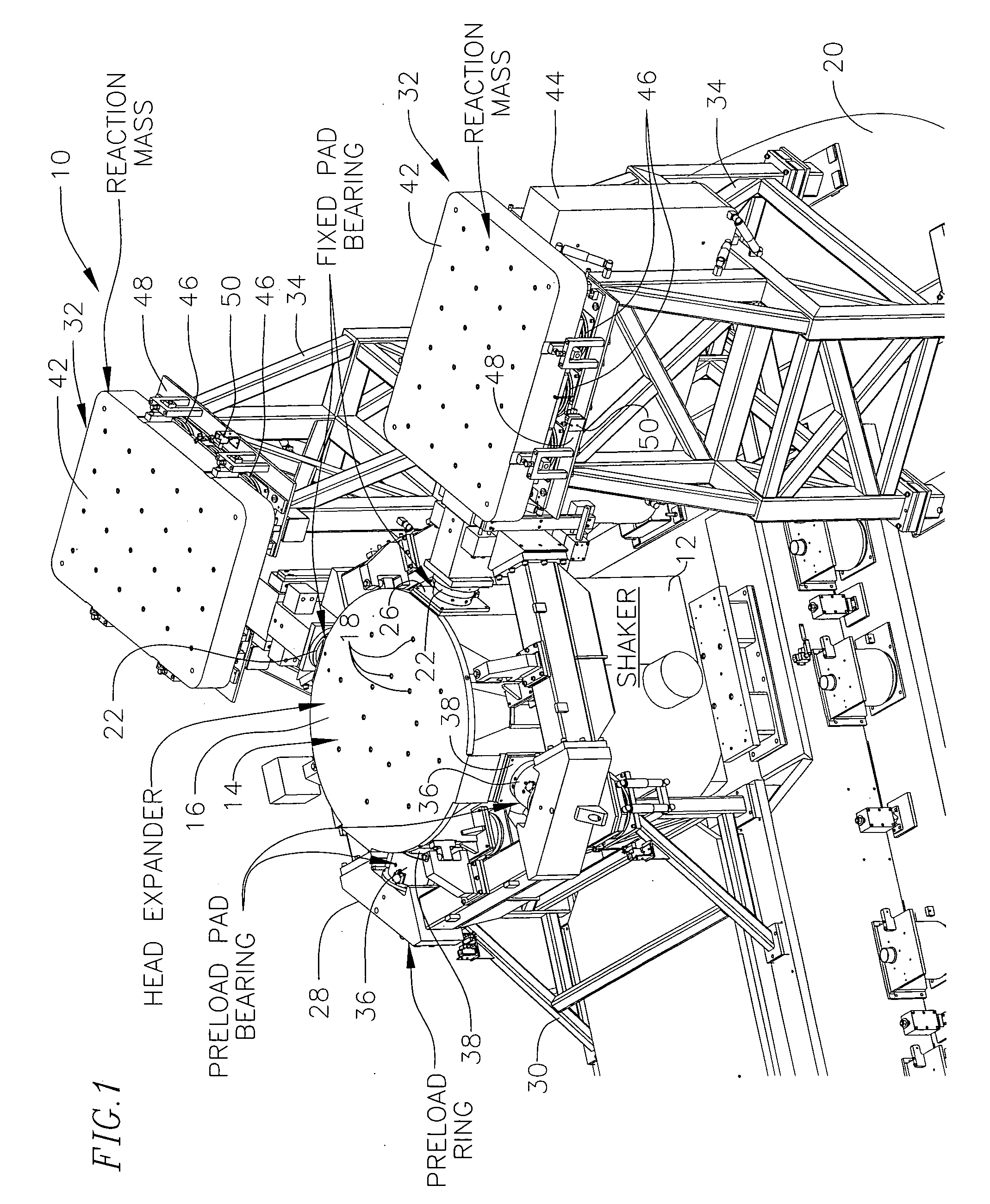
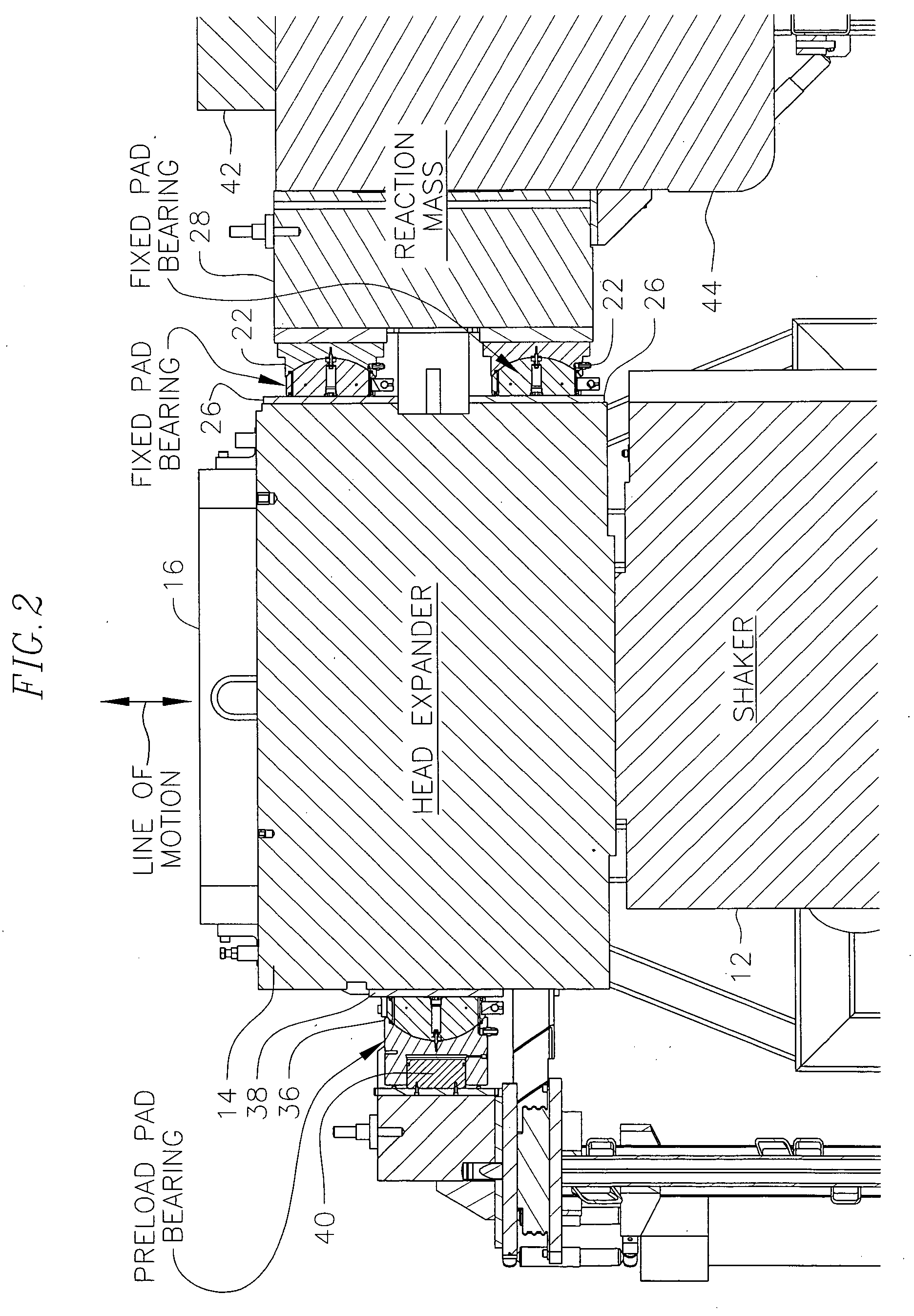
[0021] Referring to FIGS. 1 and 2, a single linear axis vibration test system 10 comprises a vibration generator or shaker 12 for applying vibrational energy to a test object (not shown) affixed to a head expander 14 on the vibration generator. The vibration generator preferably comprises an electro-dynamic shaker, and one example is the T-4000 manufactured by Unholtz-Dickie. Other types of vibration force generators can be used. Electro-hydraulic and mechanical are two common alternatives.

[0022] In the illustrated embodiment, the shaker carries the head expander 14 for increasing the mounting area of the shaker. Payloads of large footprints can be safely mounted and tested using the head expander.

[0023] The head expander 14 is generally cylindrical in shape and comprises a series of round metal plates welded together and supported on a structure comprised of metal ribs which extend radially and are spaced at 45° angles. Head expander shapes are quite variable. They may be round, ...


PUM


Abstract

A single axis vibration test system includes a vibration force generator or “shaker” which optionally can be used with a head expander, and separate pairs of hydrostatic self-aligning sliding bearings connecting two large reaction masses to the head expander. Preload forces are applied by separate preload pistons supported on a preload ring surrounding the shaker. Preload forces are transmitted by the preload ring to the sliding bearings to clamp the head expander directly to the reaction masses, which resists lateral and rotational motions during vertical axis testing. The reaction masses are supported on resilient supports carried on a sub-structure rigidly affixed to ground, avoiding a rigid connection between the preload ring and ground which in turn avoids unwanted mechanical resonances within the operational frequency range of the system during use.

Description

FIELD OF THE INVENTION [0001] This invention relates to vibration test machines, and more particularly, to an improved single linear axis vibration test system. One application of the invention is for a vertical linear axis vibration tester. BACKGROUND OF THE INVENTION [0002] Vibration test machines (also referred to as “shakers”) have been used in the past for applying vibrational test loads to a test object to simulate the vibration experienced during actual use conditions. Such vibration test systems have application to the military, aeronautics, aerospace, satellite communications, automotive, and electronics industries, i.e., for providing nondestructive testing of components or devices eventually subjected to vibrational motions during use. One example is testing to simulate the vibration forces of a launch vehicle on a communications satellite. One critical vibration test for communication satellites, as an example, involves use of a single axis vibration test system for test...

Claims


Application Information

Patent Timeline
IPC IPC(8): B06B3/00
CPCG01M7/04G01M7/027
Inventor LUND, DOUGLAS A.
Owner TEAM
Why Eureka
Try Eureka