
Hole plugs

a technology of hole plugs and plugs, which is applied in the field of hole plugs, can solve the problems of excessive expansion of the sealing area of the cover portion, inability to provide sufficient sealing performance of the hole plug of this type, and inability to readily insert the fixing portion into the through-hol

Inactive Publication Date: 2007-03-22
DAIWA KASEI IND CO LTD
View PDF3 Cites 17 Cited by
  • Summary
  • Abstract
  • Description
  • Claims
  • Application Information

AI Technical Summary

Benefits of technology

[0012] The configuration maintaining means may be formed such that a sliding frictional force can be produced between the peripheral edge portion of the cover portion and the other side surface of the compartment wall so as to restrict the movement of the cover portion relative to the compartment wall. Also, the configuration maintaining means may be formed by appropriately selecting the shape and the material of the peripheral edge portion or the portion in the vicinity of the peripheral edge portion such that the portion may have an increased deformation resistance against a compression force (an increased hoop stress).
[0015] According to the second embodiment of the invention, the cover portion is integrally formed of elastomer as a unit. Further, the portion formed with the configuration maintaining means is thickened. Therefore, such a portion can increase the deformation resistance (an increased hoop stress), more so than a portion formed with the elastic force imparting means. Therefore, the external force can be easily concentrated to the portion formed with the elastic force imparting means.
[0017] According to the third embodiment of the invention, the portion formed with the configuration maintaining means of the cover portion has the V-shaped configuration in cross section. Therefore, it is possible to reliably keep a sealing posture with respect to the other surface (contact surface) of the compartment wall. Accordingly, the elastic force can stably contact the other surface. Further, the double seal structure may increase sealing performance of the cover portion.
[0018] The present invention may provide the following effects. First, according to the first embodiment of the invention, when the hole plug is inserted into the through-hole, the peripheral edge portion of the cover portion is not widened (i.e., is not outwardly expanded). Therefore, the diameter of a sealing area of the cover portion can be reduced. Further, as the hole plug is inserted into the through-hole, the cover portion is deformed while undergoing elastic buckling. Thus, the force required for inserting the hole plug may be reduced. Also, due to the change in the elastic force caused by the elastic buckling, an appropriate crisp actual engagement feeling can be obtained. As a result, the attaching operation of the hole plug can be facilitated.
[0019] Next, according to the second embodiment of the invention, the cover portion can be formed by the integral molding of elastomer. Therefore, the second invention may have increased sealing performance in addition to the effect of the first invention.
[0020] Next, according to the third embodiment of the invention, due to the elastic repulsive force generated in the cover portion, the peripheral edge portion of the cover portion may stably contact the other surface of the compartment wall. Therefore, the sealing performance can be stabilized.

Problems solved by technology

However, in these conventional devices, when the hole plug is attached to the panel, often times, the attaching portion cannot be readily inserted into the through-hole and reliably engage the panel.
Further, in some cases, the hole plug of this type cannot provide sufficient sealing performance (waterproof property and dustproof property).
Further, when the hole plug is attached, the diameter of a sealing area of the cover portion may be excessively increased.
Therefore, when the worker inserts the umbrella-shaped portion of the attaching portion into the through-hole of the panel, the worker cannot have a crisp actual engagement feeling as to whether the umbrella-shaped portion is restored in the through-hole (as to whether the portion is reliably engaged to the panel inner surface).
Thus, it is impossible to crisply feel as to whether the attaching portion has been completely inserted.
Therefore, it is difficult to insert the attaching portion into the through-hole.
In addition, if the umbrella-shaped cover portion is elongated, an extent of the cover portion (the diameter of the sealing area of the cover portion) may be unnecessarily increased when the hole plug is attached to the panel.
Consequently, such a hole plug cannot be used in a place where there is not a sufficient space for the hole plug.

Method used


Image

  • Hole plugs
  • Hole plugs
  • Hole plugs

Examples


first embodiment

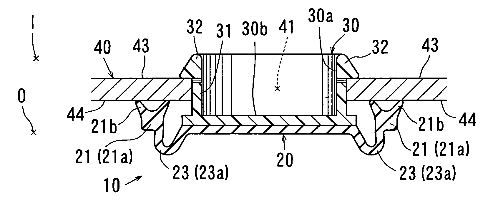
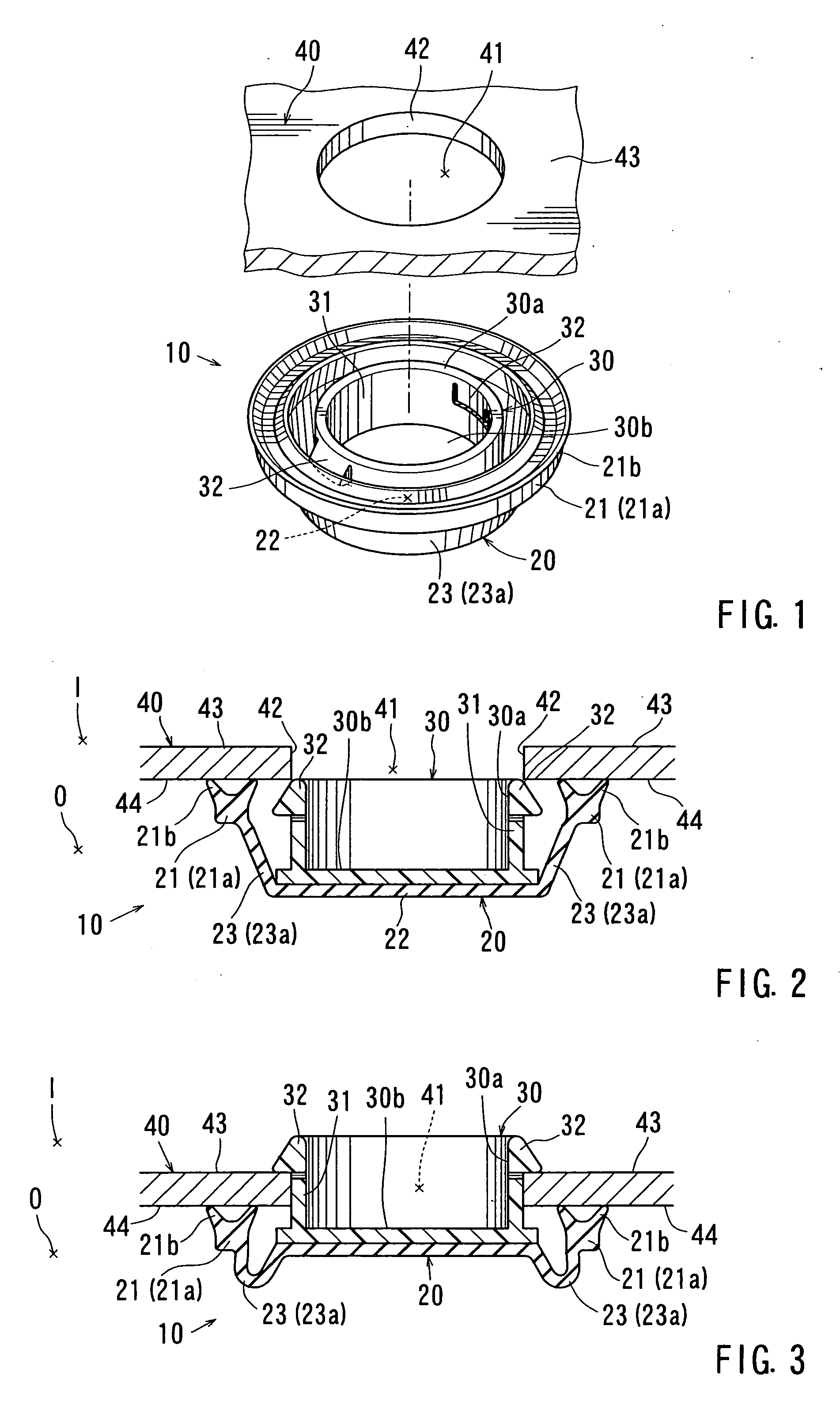
[0033] Detailed representative embodiments of the present invention are described with reference to the drawings. FIGS. 1 to 3 show a hole plug 10 according to the present invention. FIG. 1 is a perspective view of the hole plug 10. FIG. 2 is a cross-sectional view of the hole plug 10, which illustrates a condition before the hole plug 10 is inserted into a through-hole 41 formed in a compartment wall or panel 40. FIG. 3 is a cross-sectional view of the hole plug 10, which illustrates a condition after the hole plug 10 is inserted into the through-hole 41 formed in the compartment panel 40. Further, in FIGS. 2 and 3, references I and O respectively indicate inner and outer sides of the compartment panel 40.

[0034] It is noted that an example of the compartment panel 40 is a door panel of a vehicle. Also, the through-hole 41 corresponds to one of the through-holes that are formed in the compartment panel 40 at the time of the production thereof and the through-hole is otherwise left o...

second embodiment

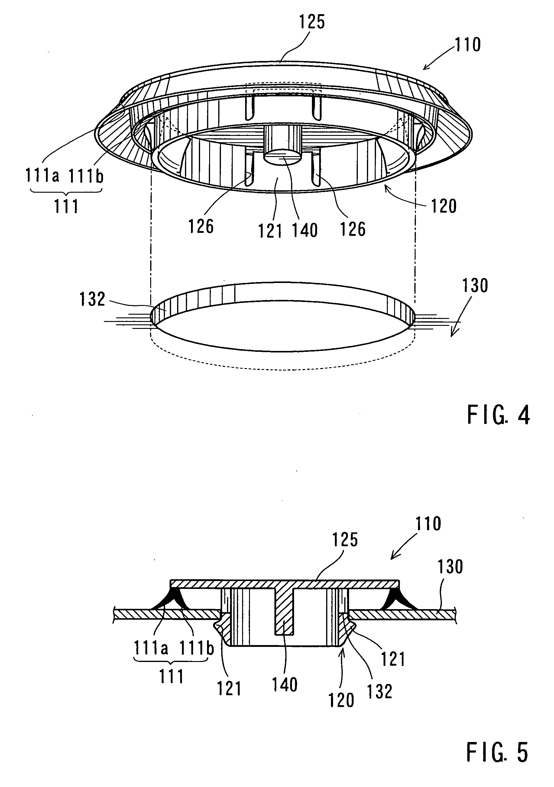
[0079] Moreover, in the second embodiment, the hole 132 formed in the body member 130 has a circular shape. However, the hole 132 may have a rectangular shape. Similarly, the seal members 111a and 111b of the seal member 111 have a circular shape. Naturally, the seal members 111a and 111b can be modified so as to correspond to the shape of the hole 132. Further, it should be noted that the seal members must be continuously formed regardless of the shape thereof.


PUM


Abstract

A hole plug for closing a through-hole formed in a compartment wall may include an attaching portion formed from a synthetic resin and a cover portion integrated with the attaching portion at a central portion thereof. The attaching portion can be inserted into the through-hole so as to engage the inner surface of the compartment wall. The cover portion has a size and shape that can enclose the through-hole and has a peripheral edge portion that can closely contact the outer surface of the compartment wall. The cover portion has a thickened portion that is formed in the peripheral edge portion thereof or in a vicinity of the peripheral edge portion and that can maintain a size and configuration of the peripheral edge portion when an external force is applied to the cover portion. The cover portion has a thinned portion that is formed between the thickened portion and the central portion integrated with the attaching portion and that can undergo elastic buckling deformation when an external force is applied thereto.

Description

[0001] This is a continuation of International Patent Application PCT / JP2005 / 009149, filed May 19, 2005, which claims priority of Japanese Patent Application S.N. 2004-153438, filed May 24, 2004.FIELD OF THE INVENTION [0002] The present invention relates to hole plugs. More specifically, the present invention relates to hole plugs for sealing through-holes that are formed in various portions of a structure of a vehicle such as an automobile and which through-holes are otherwise left open without being used. BACKGROUND OF THE INVENTION [0003] A hole plug of this type is inserted into a through-hole, which is formed in a portion (e.g., a compartment wall) of a vehicle body or the like at the time of the production thereof and is otherwise left open without being used, to thereby seal the through-hole. Therefore, when the hole plug is to be applied to a through-hole formed in a portion (e.g., an inner panel) of a door that separates a vehicle interior from a vehicle exterior, the hole ...

Claims


Application Information

Patent Timeline
Patent Type & Authority Applications(United States)
IPC IPC(8): B65D43/08B60R13/06B60R13/08F16J13/14
CPCB60R13/06B62D25/24B60R13/0846
Inventor IWAHARA, TOSHIO
Owner DAIWA KASEI IND CO LTD
Learn More