
Vacuum assisted resin transfer molding techniques with flow flooding chamber

a technology of flow flooding chamber and vacuum assisted resin, which is applied in the direction of layered products, chemistry apparatus and processes, manufacturing tools, etc., can solve the problems of addition waste, superfluous permanent features, and cos

Inactive Publication Date: 2007-03-22
UNIVERSITY OF DELAWARE
View PDF17 Cites 57 Cited by
  • Summary
  • Abstract
  • Description
  • Claims
  • Application Information

AI Technical Summary

Benefits of technology

[0007] An object of this invention is to provide a solution which circumvents the need for a distribution media to achieve low injection times. Thus the desired composite part can be created with injection times that are comparable to when one uses a distribution media but as our process does not use the distribution media there is no wasted material in terms of distribution media and peel ply and in addition there is time and labor savings as one does not have to manually place the peel ply and distribution media on top of the preform and remove it after the part has cured. There is also saving in the resin quantity used as most of the resin that goes into the distribution media and the peel ply is wasted.
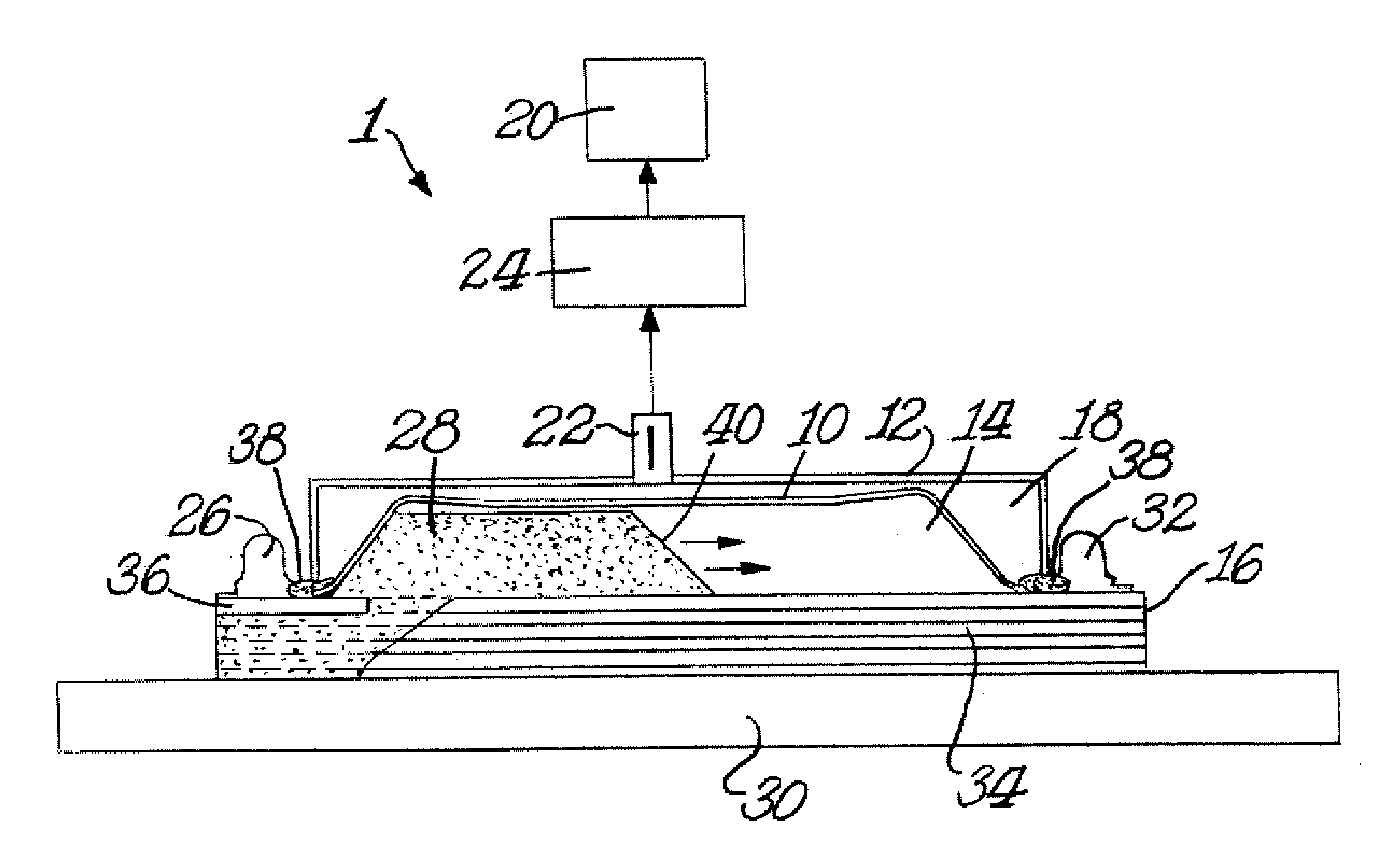
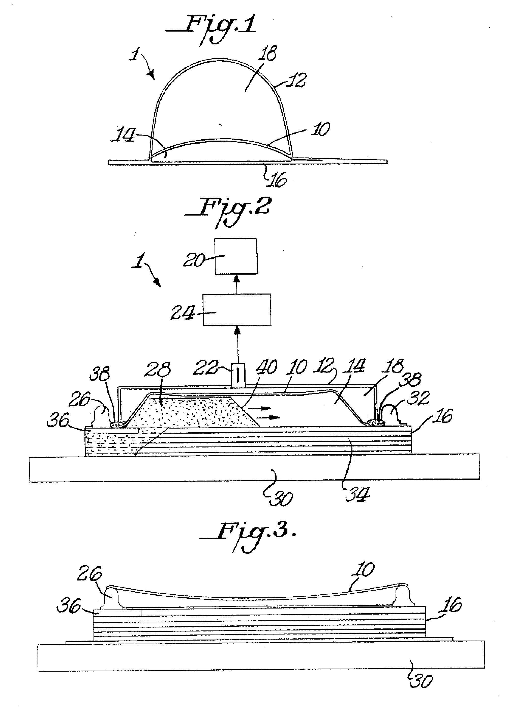
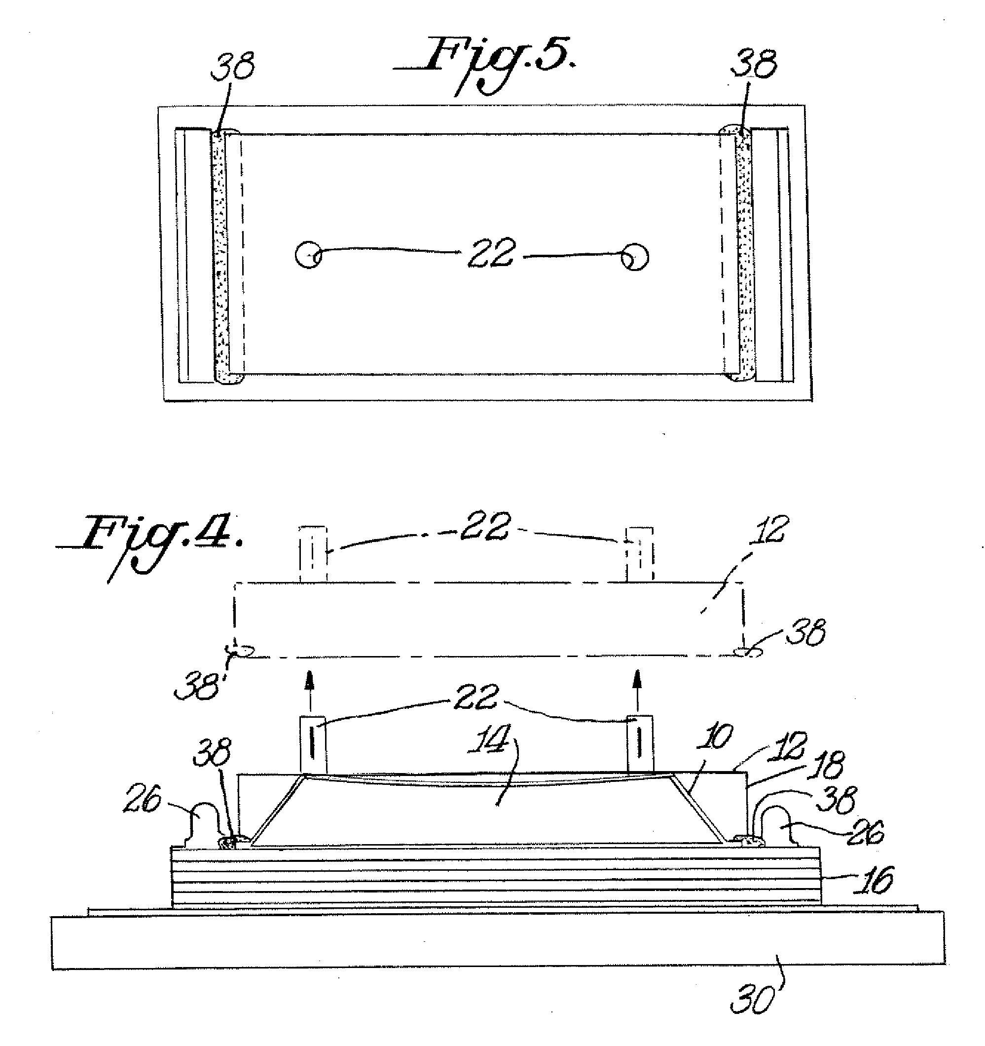
[0008] In accordance with this invention a flow channel is placed on the top face of the fabric preform creating a Flow Flooding Chamber (FFC) to accelerate the resin flow and reduce the injection time. To accomplish this, we locally lift the bag using a rigid, external vacuum chamber, which is placed on top of the bag during injection.

Problems solved by technology

The effect of the distribution media is to decrease filling time and improve the resin delivery but its use is not always feasible or can result in a superfluous permanent feature in the final composite part.
After the part cures, the distribution media along with the peel ply are peeled away from the part and thrown away which causes addition waste and cost.

Method used


Image

  • Vacuum assisted resin transfer molding techniques with flow flooding chamber
  • Vacuum assisted resin transfer molding techniques with flow flooding chamber
  • Vacuum assisted resin transfer molding techniques with flow flooding chamber

Examples


Embodiment Construction

[0013] This application is based upon provisional application Ser. No. 60 / 719,508, filed Sep. 22, 2005, all of the details of which are incorporated herein by reference thereto.

[0014] The present invention is directed to replacing the conventional distribution media and associated peel ply in VARTM. This results in the cost advantages related to omitting the distribution media such as shipping, storage and non-cycleable trash. Moreover, the distribution media can not always be used because, for example, particles in resin suspension can not penetrate the peel ply and the distribution media must become a permanent feature of the finished part or not be used at all.

[0015] The basic concept of this invention, as illustrated in FIG. 1, is to create a flow channel on the top face of the fabric 16 to accelerate the resin flow and reduce the injection time. As illustrated in FIG. 1 this is accomplished in unit 1 by locally lifting the vacuum bag 10 through the use of a rigid external vac...


PUM

PropertyMeasurementUnit
filling timeaaaaaaaaaa
permeabilityaaaaaaaaaa
pressureaaaaaaaaaa

Abstract

Vacuum assisted resin transfer molding techniques are improved by mounting a rigid external shell on top of a vacuum bag. The shell is sealed around the vacuum bag so that a vacuum is created between the shell and the vacuum bag, the vacuum causes the vacuum bag to be freely stretched and lifted away from the preform to create a flow flooding chamber which provides a flow channel on the top face of the preform to accelerate the resin flow and reduce the injection time.

Description

CROSS REFERENCE TO RELATED APPLICATION [0001] This application is based on provisional application Ser. No. 60 / 719,508, filed Sep. 22, 2005.GOVERNMENT LICENSE RIGHTS [0002] The United States government has rights in this invention which was done under funding by Office of Naval Research under Grant N00014-03-1-0891.BACKGROUND OF INVENTION [0003] This invention relates to the resin delivery in a composite manufacturing process called Vacuum Assisted Resin Transfer Molding (VARTM). [0004] VARTM is a subclass of Liquid Composite Molding process, which is a method to deliver the resin to cover and saturate the fiber preform and subsequently cure the resin. One must saturate the preform before it begins curing as after the resin starts to cure the viscosity of the resin increases preventing any further impregnation. [0005] VARTM is commonly used to manufacture polymer composite parts due to its simplicity, ability to yield near-net-shaped parts, and low equipment and tooling costs. In VA...

Claims


Application Information

Patent Timeline
Patent Type & Authority Applications(United States)
IPC IPC(8): B29C70/00
CPCB29C70/443B29C70/548B29C70/546
Inventor VERNIN, NICOLASCHOHRA, MOURADADVANI, SURESHALMS, JUSTIN
Owner UNIVERSITY OF DELAWARE
Learn More