Apparatus for clamping work pieces

a technology for clamping work pieces and work pieces, applied in the direction of positioning apparatus, metal-working holders, supports, etc., can solve the problems of high cost and time-consuming production of such devices, and achieve the effects of low cost, high degree of immunity against contamination, and quick machined

Inactive Publication Date: 2007-03-22
F TOOL INT
View PDF1 Cites 23 Cited by
  • Summary
  • Abstract
  • Description
  • Claims
  • Application Information

AI Technical Summary

Benefits of technology

[0004] It is an object of the present invention to provide a clamping apparatus for clampingly retaining a work piece having a polygonal shaft in a positionally well defined manner that can be manufactured easily, quickly and particularly at very low costs without affecting the positional accuracy of clamping of the work piece to be clampingly retained in the apparatus to a noteworthy degree. SUMMARY OF THE INVENTION
[0007] Thus, one of the fundamental ideas of the invention is to manufacture the clamping body member of a base material that can be machined quickly, easily and, thereby, a low costs, while the few elements required for an accurate positioning in X- and / or Y-directions are made of a substantially harder material.
[0008] Preferably, the stop pin members are of cylindrical shape; thus, commercially available already finished round blanks can be used for manufacturing the stop pin members. A further advantage of cylindrical stop pin members may be seen in the fact that a work piece having flat lateral surfaces rests on the stop pin members along a line only, thus providing a high degree of immunity against contamination.

Problems solved by technology

Even if this apparatus is rigid and stable and provides for a high repetitional accuracy, its production is very time consuming and costly.

Method used


Image

  • Apparatus for clamping work pieces
  • Apparatus for clamping work pieces
  • Apparatus for clamping work pieces

Examples


Embodiment Construction

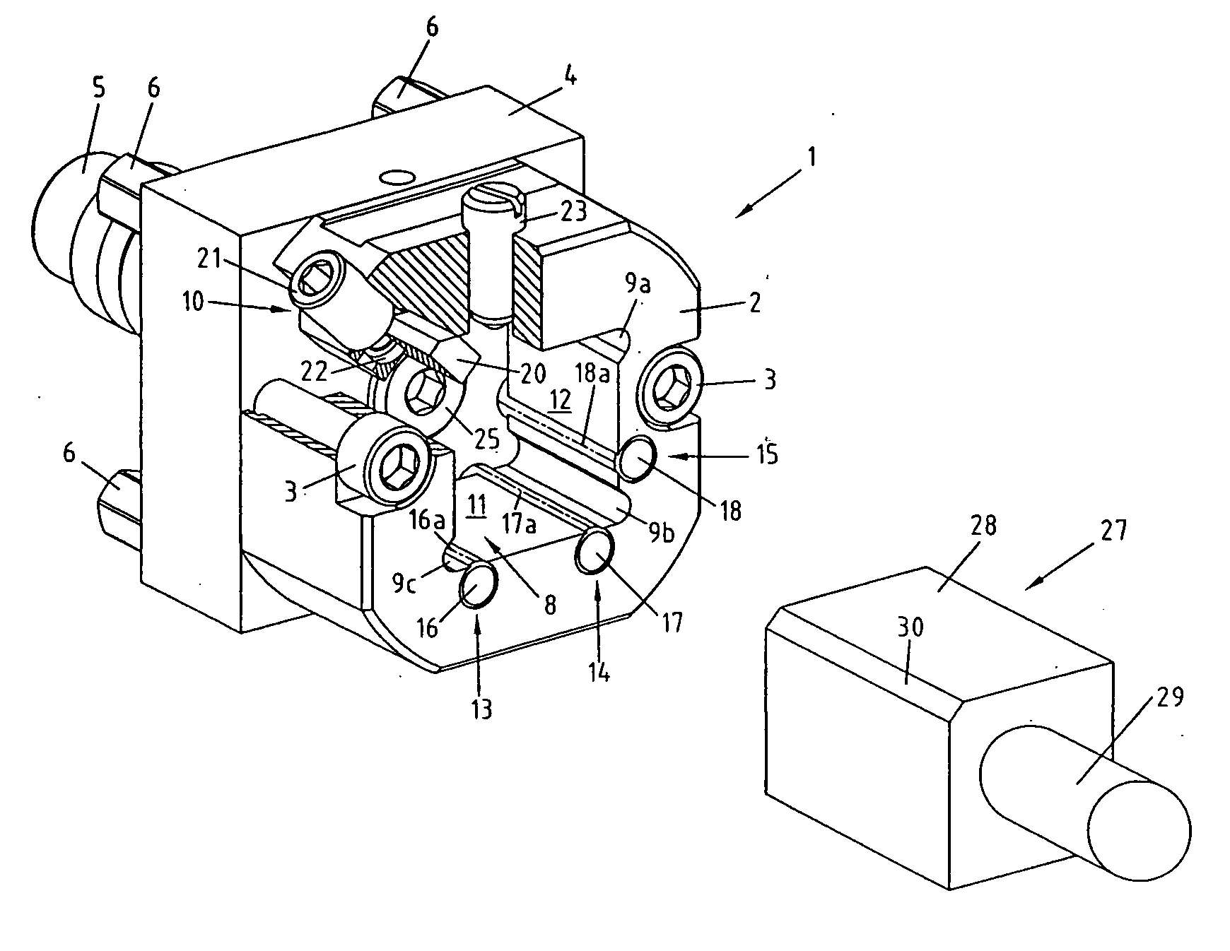
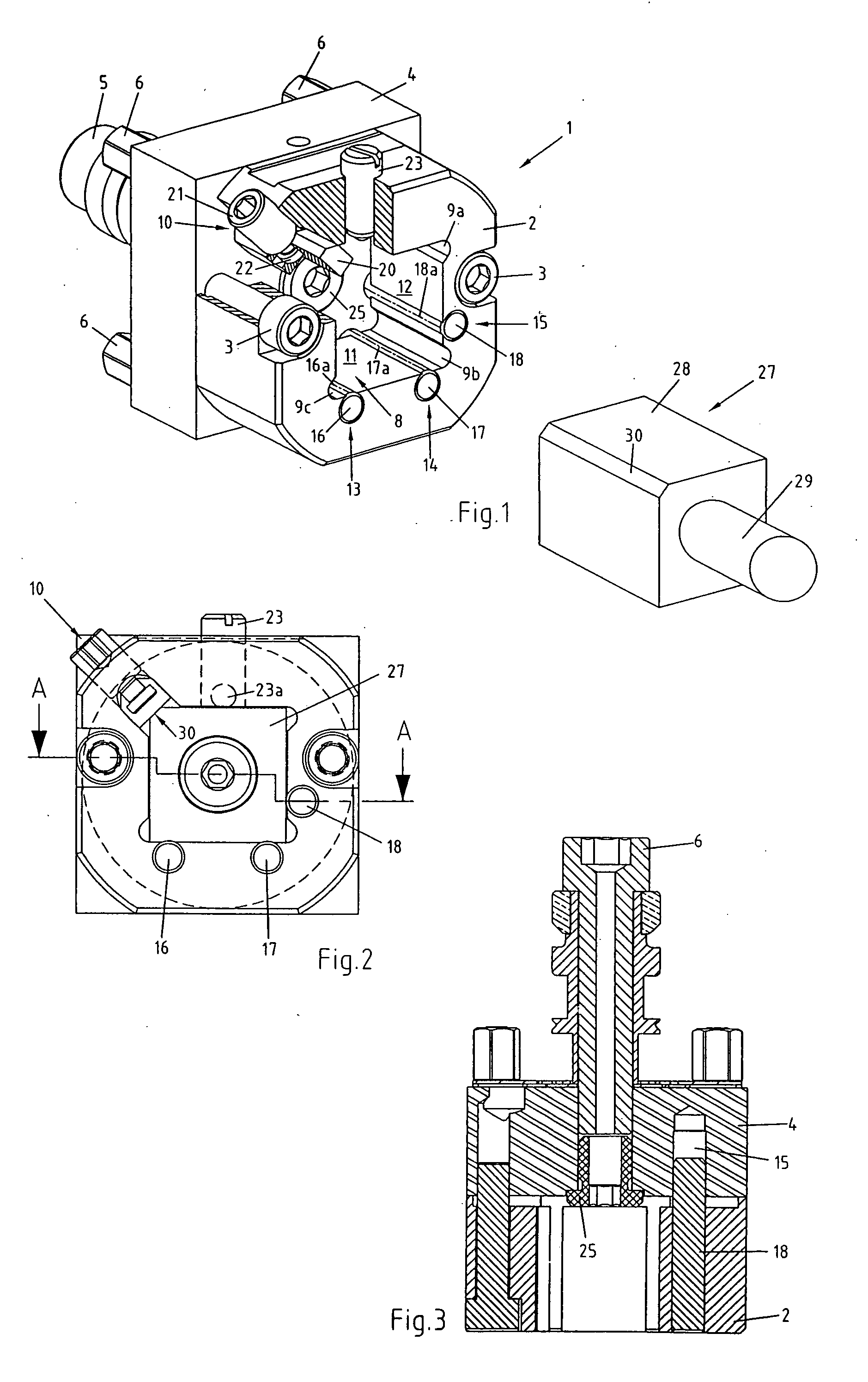
[0015]FIG. 1 shows a perspective, partially sectioned view of a clamping apparatus 1 for clampingly retaining a work piece 27, illustrated as an example, in the present case for instance an electrode for electro erosive machining. The schematically illustrated clamping apparatus 1 comprises a clamping body member 2 attached to a base plate 4 by means of screws 3. The base plate 4 is provided with a draw bar 5 by means of which it can be clampingly fixed to a clamping chuck (not shown). Moreover, the base plate 4 is provided with support pins 6 as well as with (not shown) centering and positioning elements, by means of which an accurate alignment of the base plate 4, and thereby also of the clamping body member 2, with regard to the clamping chuck of the machine tool is ensured.

[0016] A clamping chamber 8 is provided in the interior of the clamping body member 2, having a polygonal cross section. In the present example, the cross section of the clamping chamber 8 is substantially sq...


PUM

PropertyMeasurementUnit
cylindrical shapeaaaaaaaaaa
shapeaaaaaaaaaa
diameteraaaaaaaaaa

Abstract

The clamping apparatus provides for a positionally accurate clamping of a work piece having at least one shaft with a polygonal cross section. To this end, the clamping apparatus is provided with a clamping body member, having a clamping chamber with polygonal cross section adapted to receive the shaft of the work piece. The clamping body member is provided with clamping means to clampingly fix the shaft to the clamping body member, and with reference surfaces for determining the position of the work piece in X- and Y-directions. The reference surfaces are constituted by stop pin members inserted into bores provided in the clamping body member, whereby the stop pin members are made of a material that is harder than the material of the clamping body member. The stop pin members are of cylindrical shape, whereby the bores receiving the stop pin members open into the clamping chambers such that a small portion of each stop pin member protrudes into the interior of the clamping chamber.

Description

BACKGROUND OF THE INVENTION [0001] The present invention refers to a clamping apparatus for clampingly retaining a work piece having a shaft with polygonal cross section in a well defined position. It comprises a clamping body member with a clamping chamber adapted to receive the shaft of the work piece, clamping means for clampingly retaining the shaft of the work piece in the clamping chamber, and reference surface means provided on the clamping body member for defining the position of the shaft clampingly retained in the clamping chamber in X-direction and / or in Y-direction. [0002] Clamping apparatuses of the kind referred to herein serve for clampingly retaining work pieces in a well defined position, preferably in the operating region of a machine tool, whereby the expression “work piece” is used in its broadest meaning; in other words, besides conventional work pieces, that expression shall cover also for example machining tools. PRIOR ART [0003] The document EP-A-0,248,116 di...

Claims


Application Information

Patent Timeline
Patent Type & Authority Applications(United States)
IPC IPC(8): B23B31/02
CPCB23H7/26Y10T279/3487B23Q3/18B23Q3/00B23Q3/06
Inventor TROXLER, FERDINAND
Owner F TOOL INT
Why Eureka
Try Eureka