Permanent magnet type rotating electric machine capable of suppressing deformation of rotor core

a permanent magnet and electric machine technology, applied in the direction of dynamo-electric machines, electrical apparatus, magnetic circuits, etc., can solve the problems of permanent magnet damage, permanent magnet b> may wobble, etc., and achieve the effect of suppressing the deformation of the rotor cor

Active Publication Date: 2007-03-22
TOYOTA JIDOSHA KK
View PDF9 Cites 128 Cited by
  • Summary
  • Abstract
  • Description
  • Claims
  • Application Information

AI Technical Summary

Benefits of technology

[0017] An object of the present invention is to provide a permanent magnet type ro

Problems solved by technology

However, with such a fixing method of permanent magnets, when fill properties of the adhesive relative to openings 120 of rotor core 100 is poor, permanent magnets 130 may wobble due to centrifugal force acting on permanent magnets 130 when the rotating electric machine is started or stopped, or when the load abruptly changes.
This wobbling may lead to a damage of permanent magnets 130.
Rotor core 100 may also be damaged due to stress concentration at the portion where the adhesive is placed.
Further, for filling openings 130 with the adhesive, complicated administration is necessary as to the temperature of the adhesive and rotor core 100, the dimension of a gap between them, and a work posture, and therefore there has been a problem of poor workability.
Howeve

Method used


Image

  • Permanent magnet type rotating electric machine capable of suppressing deformation of rotor core
  • Permanent magnet type rotating electric machine capable of suppressing deformation of rotor core
  • Permanent magnet type rotating electric machine capable of suppressing deformation of rotor core

Examples


first embodiment

[0046] First Embodiment

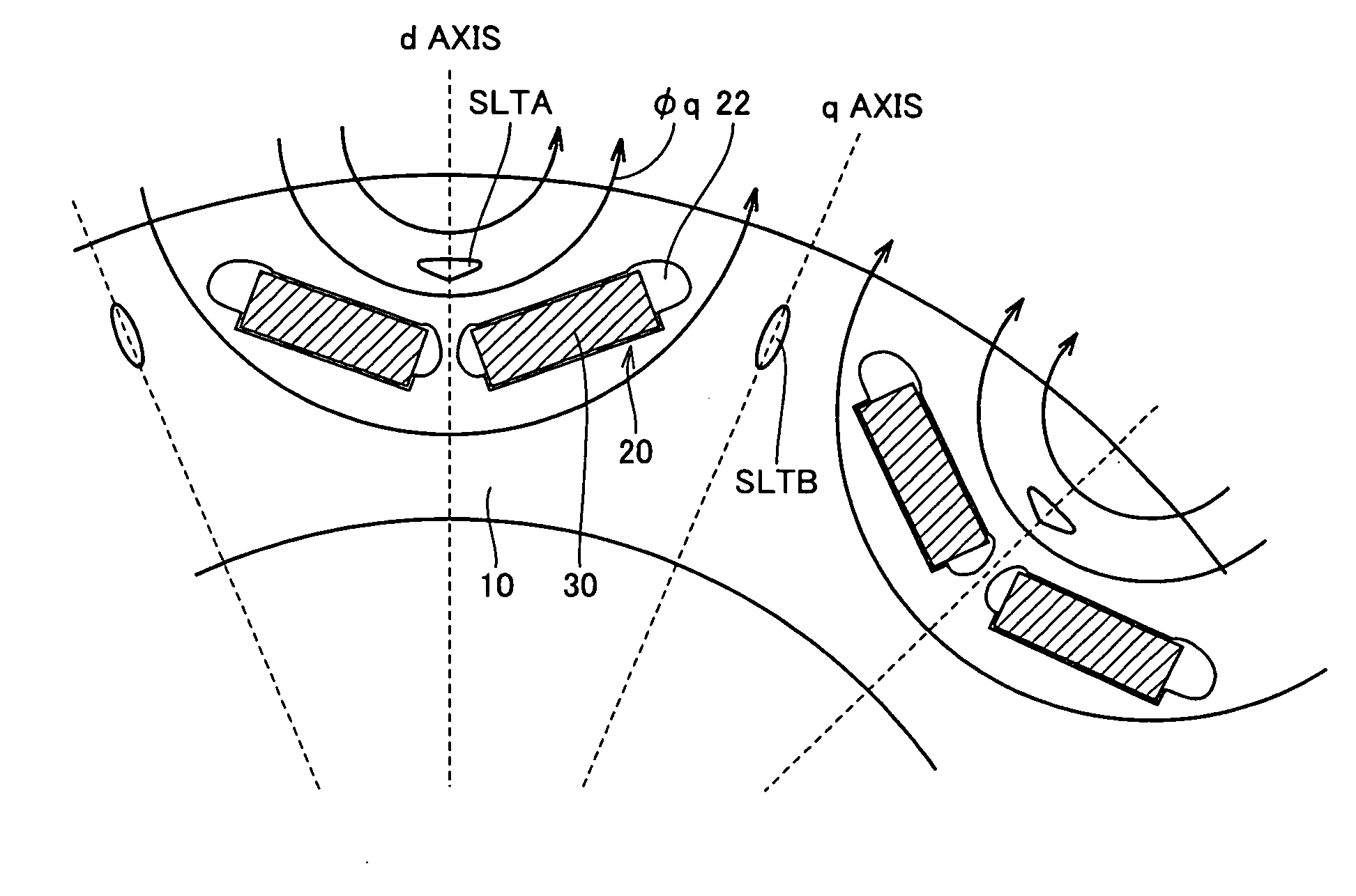
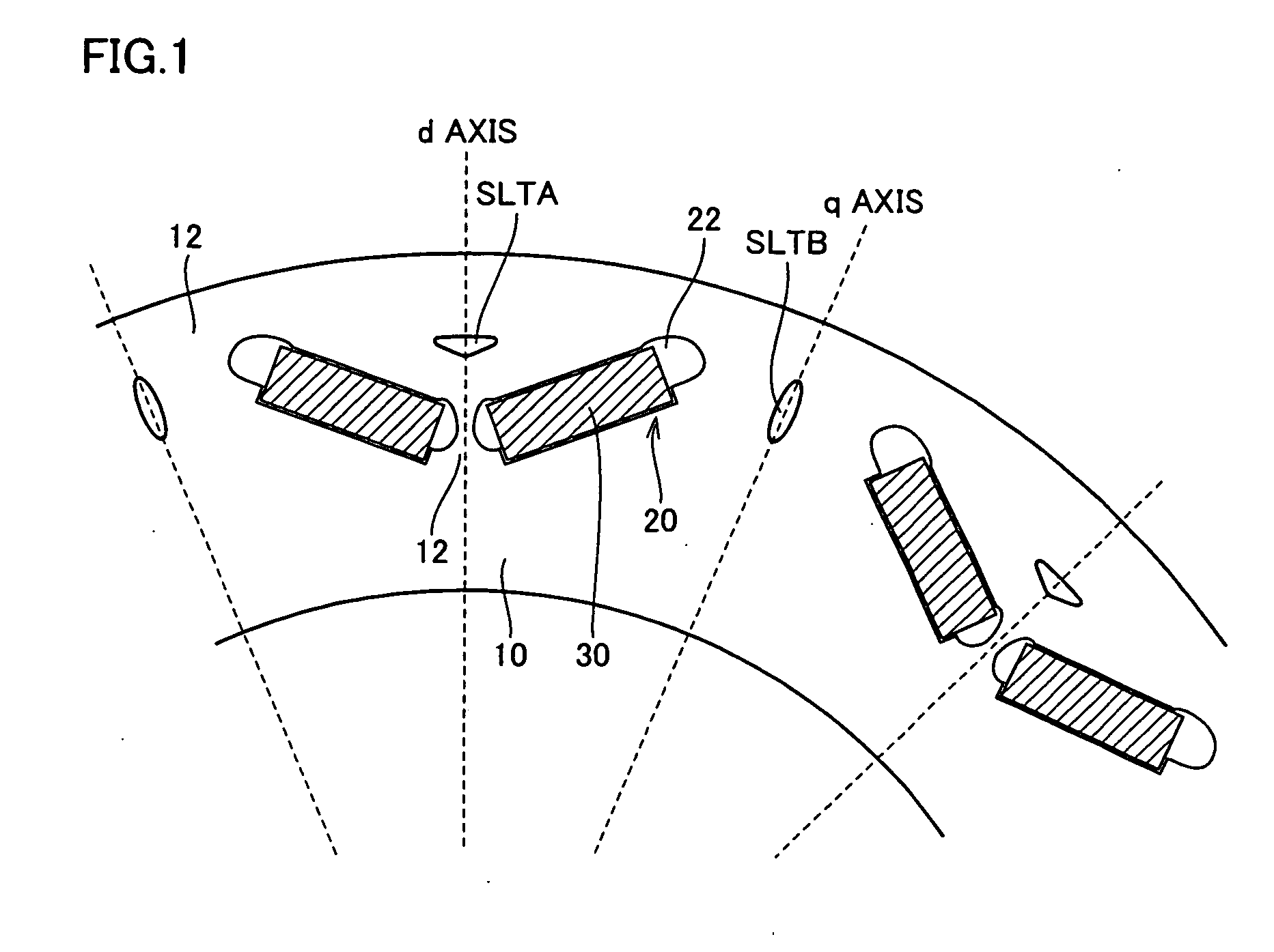
[0047]FIG. 1 is an illustration for describing a structure of a rotor in a permanent magnet type rotating electric machine according to a first embodiment of the present invention. FIG. 1 is an enlarged view of the rotor when seen from the rotation shaft direction.

[0048] Referring to FIG. 1, the rotor includes a rotor core 10 provided at the outer periphery of a not-shown rotation shaft, and permanent magnets 30 arranged at rotor core 10.

[0049] Rotor core 10 is, for example, formed by a plurality of electromagnetic steel plates stacked in the rotation shaft direction of the rotor. Openings 20 are provided in a plurality of numbers along the circumferential direction of rotor core 10. When punching electromagnetic steel plates to obtain thin plates forming rotor core 10, openings 20 are punched simultaneously, and formed in parallel with the rotation shaft as the thin plates are stacked.

[0050] As shown in FIG. 1, openings 20 are arranged at the outer periphe...

first modification

[0082] First Modification

[0083]FIG. 6 is an illustration for describing a structure of a rotor in a permanent magnet type rotating electric machine according to a first modification of the first embodiment of the present invention.

[0084] Referring to FIG. 6, a rotor core 10acorresponds to rotor core 10 in FIG. 1 of which slit SLTB is replaced by a slit SLTC. Slit SLTC is similar to slit SLTB in FIG. 1 in that it is arranged on the q axis, but different in that it is arranged on the inner circumferential side of rotor core l0a.

[0085] While slit SLTC has the function of absorbing stress F1 and stress F2 similarly to slit SLTB, it's shape is greater than that of slit SLTB. This is enabled by the arrangement of slit SLTC on the inner circumferential side of rotor core 10a, which allows the shape of slit SLTC to be set not being limited by the magnetic path of the magnetic flux by the stator. That is, according to the present modification, the degree of freedom in designing the slit ca...

second modification

[0086] Second Modification

[0087]FIG. 7 is an illustration for describing a structure of a rotor in a permanent magnet type rotating electric machine according to a second modification of the first embodiment of the present invention.

[0088] Referring to FIG. 7, a single opening 20 is arranged for each magnetic pole in a rotor core 10b. That is, the rotor according to the present modification is different from the rotor shown in FIG. 1, in which the magnetic pole is formed by a pair of permanent magnets 30 arranged in a V-shape, in that the magnetic pole is formed of a single permanent magnet arranged as inserted into single opening 20.

[0089] In such a configuration of the rotor, in order to absorb stress acting on rotor core 10b, a slit SLTD is provided. Specifically, as shown in FIG. 6, slit SLTD is provided at the center of the magnetic pole and on the outer circumferential side of rotor core 10b.

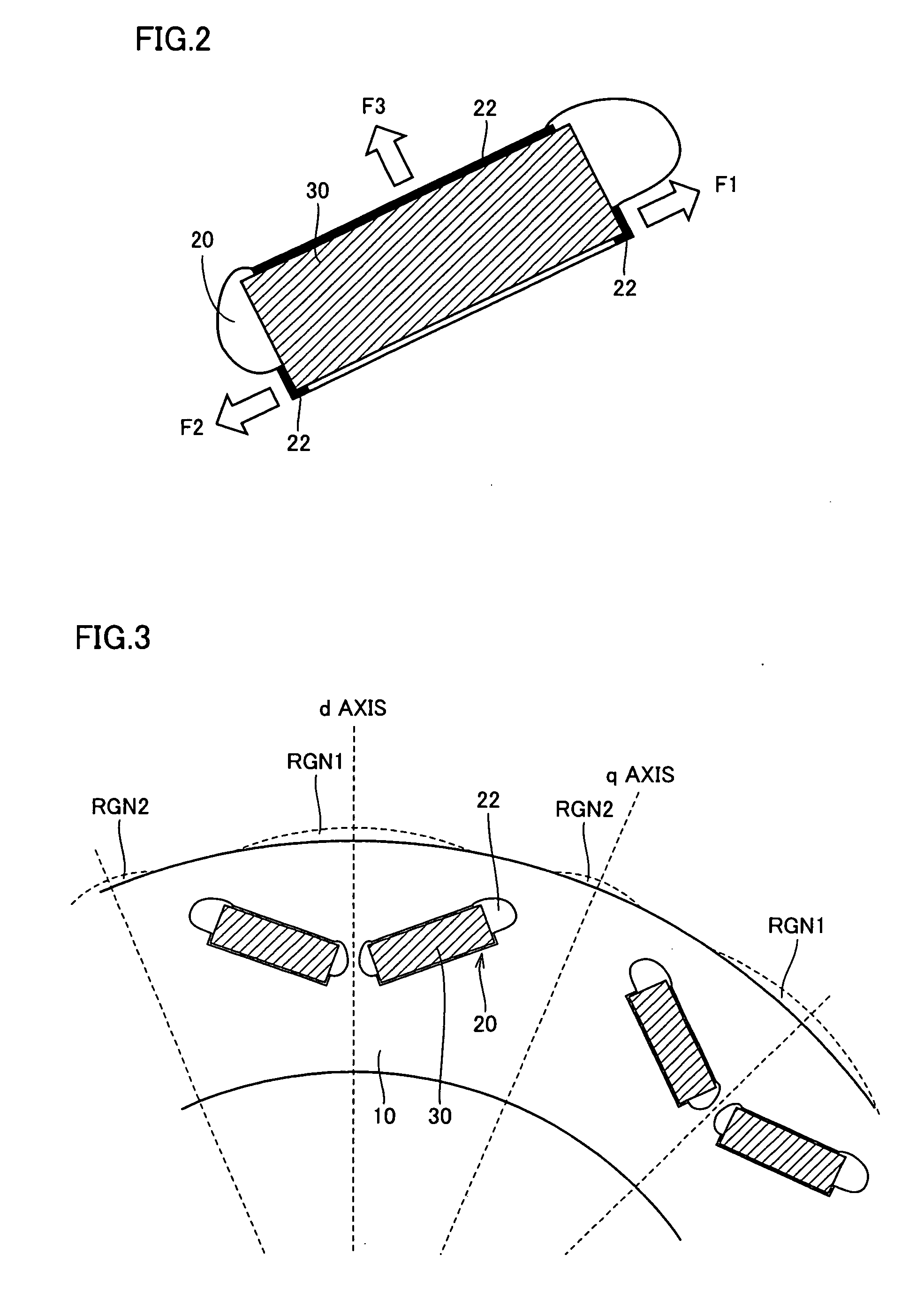
[0090] While slit SLTD has the function of absorbing stress F3 similarly to slit SL...


PUM


Abstract

A rotor core is provided with a plurality of slits extending in the rotation shaft direction, independently of openings. The first slit is arranged at the center of the magnetic pole of the rotor core to be capable of absorbing stress acting on an inner circumferential surface of each opening in a direction normal to a main surface of a permanent magnet. The second slit is arranged between the magnetic poles of the rotor core to be capable of absorbing stress acting in parallel with the main surface of the permanent magnet. Thus, the rotor core is prevented from deforming in a radial outward direction. Further, by forming the first and second slits each in a form not interfering the magnetic path of the magnetic flux by the stator passing inside the rotor core, the motor performance is ensured.

Description

[0001] This nonprovisional application is based on Japanese Patent Application No. 2005-274343 filed with the Japan Patent Office on Sep. 21, 2005, the entire contents of which are hereby incorporated by reference. BACKGROUND OF THE INVENTION [0002] 1. Field of the Invention [0003] The present invention relates to a permanent magnet type rotating electric machine, and particularly, to a permanent magnet type rotating electric machine having permanent magnets embedded in a rotor. [0004] 2. Description of the Background Art [0005] In a rotor of a permanent magnet type rotating electric machine, for example as shown in FIG. 10, a plurality of openings 120 are provided to a rotor core 100, and permanent magnets 130 are inserted into openings 120 to create magnetic poles (for example, see Japanese Patent Laying-Open Nos. 2004-104962, 09-215236, 2002-034187, 08-237893, 2001-286109, and 2004-254466). Then, the rotor is driven to rotate based on a rotating magnetic field created by bringing...

Claims


Application Information

Patent Timeline
IPC IPC(8): H02K21/12
CPCH02K1/2766
Inventor HATTORI, HIROYUKI
Owner TOYOTA JIDOSHA KK
Why Eureka
Try Eureka