Display

Active Publication Date: 2007-03-22
SHARP KK +1
View PDF14 Cites 10 Cited by
  • Summary
  • Abstract
  • Description
  • Claims
  • Application Information

AI Technical Summary

Benefits of technology

[0017] In view of the above state of the art, it is an object of the present invention to provide a display which can improve viewing angle dependency of contrast ratio in a wide azimuth with

Problems solved by technology

Generally, it is known that these display performance in the case of viewing obliquely is inferior to that in the case of viewing from the front.
However, in these methods, there were rooms for improvement in that when the pixel division method or the above-mentioned display mode is employed, it is necessary to modify an alignment layer, a structure of an electrode and the like and establishment of the production technology and installation of the production facilities for this modification are required, and this results in the difficulties in production and the high cost.
In addition, its effect of improving the viewing angle dependency is not sufficient.
Further, also in the optical compensation metho

Method used


Image

  • Display
  • Display
  • Display

Examples


embodiment 1

(Preparation of First Anisotropic Scattering Film)

[0183] First, a liquid resin was discharged onto a marginal area of a polyethylene terephthalate (PET) film having a thickness of 75 μm and a size of 76 mm×26 mm (Product name: COSMOSHINE (R) A4300, produced by TOYOBO Co., Ltd.) using a dispenser and then it was cured to form an isolating wall with a height of 0.2 mm. Next, a photopolymerizable composition of the following composition was added dropwise in a region surrounded the isolating wall and then it was covered with another PET film.

>

2-(perfluorooctyl)-ethylacrylate 50 parts by weight

1,9-nonanediol diacrylate 50 parts by weight

2-hydroxy-2-methyl-1-phenylpropane-1-one 4 parts by weight

[0184] Next, ultraviolet light was irradiated to the liquid film having thickness of 0.2 mm and being sandwiched on both sides between PET films, for 1 minute at the irradiation intensity of 30 mW / cm2 vertically from an epi-illumination unit of a UV spot light source (Product name: L2859-...

embodiment 2

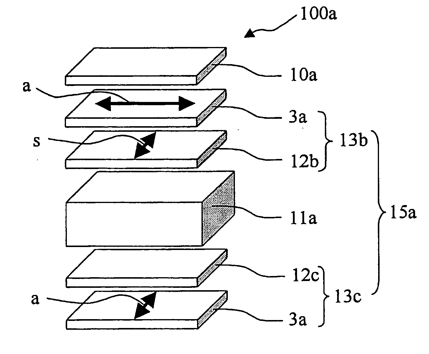
[0195]FIG. 7 is a perspective schematic diagram showing a constitution of a VA mode liquid crystal display 100a concerning Embodiment 2 of the present invention. Further, a relative positional relationship between the respective films and between the directions of axes of the respective films is as is shown in FIG. 7.

[0196] First, a second polarizing plate 13b, in which a supporting film on the VA mode liquid crystal cell 11a side was a second retardation film 12b, was bonded to a viewing screen side of the VA mode liquid crystal cell 11a prototyped in Embodiment 1 and a third polarizing plate 13c, in which a supporting film on the VA mode liquid crystal cell 11a side was a third retardation film 12c, was bonded to a backlight side of the VA mode liquid crystal cell 11a to prepare a VA mode liquid crystal display element 15a. Next, the first anisotropic scattering film 10a similar to that in Embodiment 1 was bonded to a viewing screen side of the VA mode liquid crystal display elem...

embodiment 3

[0198]FIG. 8 is a perspective schematic diagram showing a constitution of a VA mode liquid crystal display 100 concerning Embodiment 3 of the present invention. Further, a relative positional relationship between the respective films and between the directions of axes of the respective films is as is shown in FIG. 8.

[0199] First, a fourth retardation film 12d was bonded to a backlight side of the VA mode liquid crystal cell 11a prototyped in Embodiment 1, and further a first polarizing plate 13a, in which a protective film on the VA mode liquid crystal cell 11a side was TAC (triacetylcellulose) film, was bonded to a backlight side of the fourth retardation film 12d and a viewing screen side of the VA mode liquid crystal cell 11a, respectively, to prepare a VA mode liquid crystal display element 15a. Next, the first anisotropic scattering film 10a similar to Embodiment 1 was bonded to a viewing screen side of the VA mode liquid crystal display element 15a to prepare a VA mode liquid...


PUM


Abstract

The invention aims at providing a display which can improve viewing angle dependency of contrast ratio in a wide azimuth without changing design of a basic structure of a display element, impairing display quality in a direction showing large contrast ratio and being limited to a state of displaying white or black. The aim is attained by a display comprising: a display element having viewing angle dependency of contrast ratio; and an anisotropic scattering film having an anisotropic scattering layer, wherein the anisotropic scattering film has a scattering central axis approximately parallel to a direction showing the largest contrast ratio of the display element and is located on a viewing screen side of the display element.

Description

CROSS-REFERENCE TO RELATED APPLICATION [0001] This Nonprovisional application claims priority under 35 U.S.C §119 (a) on Patent Application No. 2005-273746 filed in Japan on Sep. 21, 2005 and Patent Application No. 2006-247067 filed in Japan on Sep. 12, 2006, the entire contents of which are hereby incorporated by reference. BACKGROUND OF THE INVENTION [0002] 1. Field of the Invention [0003] The present invention relates to a display and more specifically to a display such as a liquid crystal display and the like, which includes an anisotropic scattering film. [0004] 2. Description of the Related Art [0005] As a typical example of a display in which there is the dependency of display performance on the viewing angle (a viewing angle characteristic), a liquid crystal display typified by a twisted nematic (TN) mode is known. Incidentally, the term “there is the dependency of display performance on the viewing angle” means that display performance such as a contrast ratio, a gradation ...

Claims


Application Information

Patent Timeline
IPC IPC(8): G02F1/1335
CPCG02F1/133504G02F1/1335
Inventor HASEGAWA, MASAHIROSAKAI, AKIRAHIGASHI, KENSAKUKATAGIRI, HIROTO
Owner SHARP KK
Why Eureka
Try Eureka