Image projecting apparatus having variable stop

Inactive Publication Date: 2007-03-22
KONICA MINOLTA OPTO
View PDF6 Cites 37 Cited by
  • Summary
  • Abstract
  • Description
  • Claims
  • Application Information

AI Technical Summary

Benefits of technology

[0011] According to the present invention, the change in the quantity of light passing through the variable stop is greater than the change in the size of the effective region of the stop aperture from before to after the aperture setting and, therefore, even if the aperture setting is performed through the variable stop, it is possible to suppress reduction in the number of secondary-light-source images passing through the variable stop due to the aperture setting. As a result, it is possible to maintain the uniform illumination effect of the integrator. Further, it is possible to perform the aperture setting through the variable stop in such a manner as to prevent the F number of

Problems solved by technology

This will degrade uniform illumination effect of the integrator.
Furthermore, if the aperture setting is performed through the variable stop, the F number of a projection system increases to increase a depth of

Method used


Image

  • Image projecting apparatus having variable stop
  • Image projecting apparatus having variable stop
  • Image projecting apparatus having variable stop

Examples


Example

[0022] Hereinafter, with reference to the drawings, there will be described embodiments and the like of an image projecting apparatus according to the present invention. Same reference signs are designated to same or corresponding portions throughout the respective embodiments and the like, and redundant descriptions thereof will not be repeated.

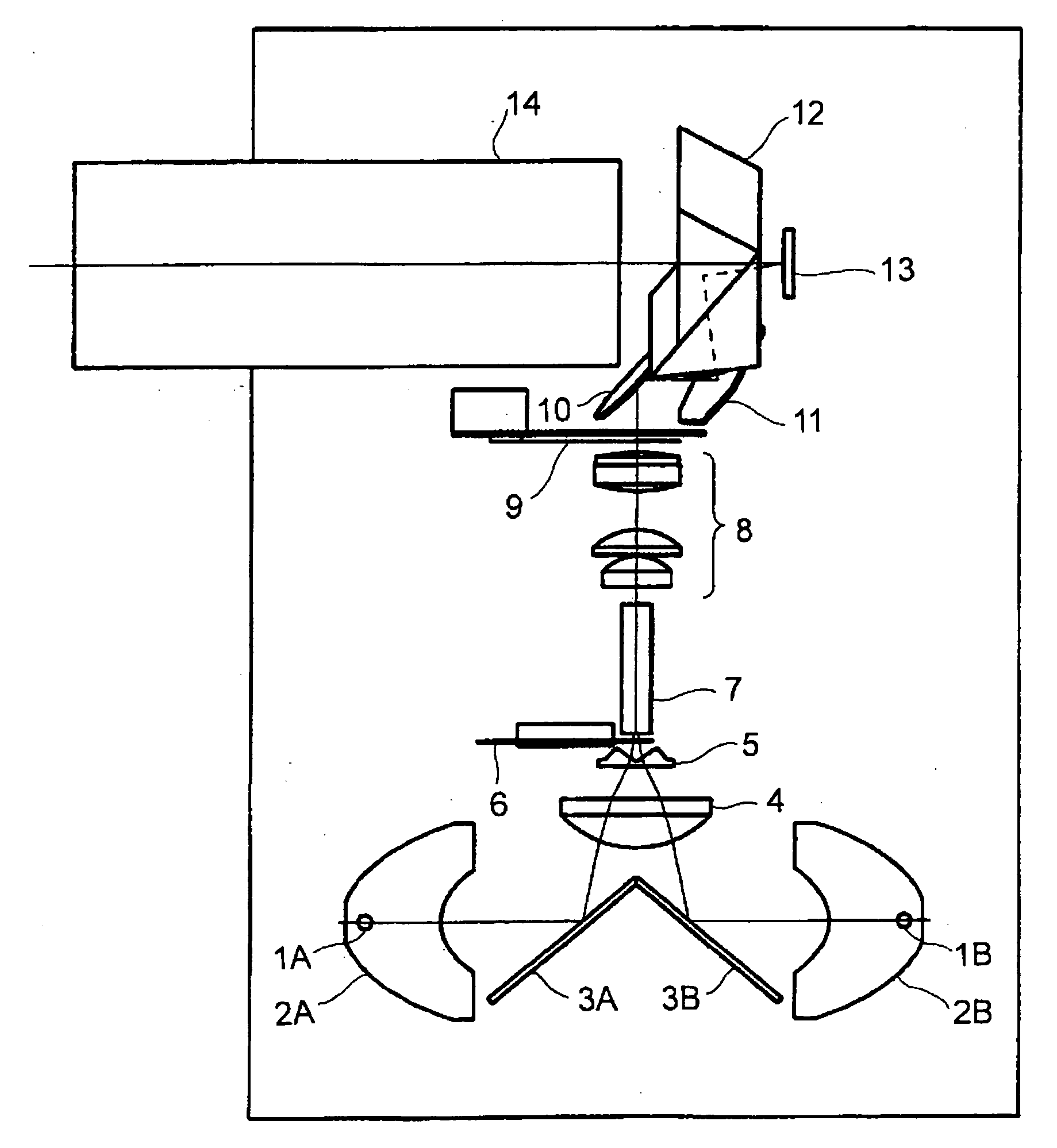
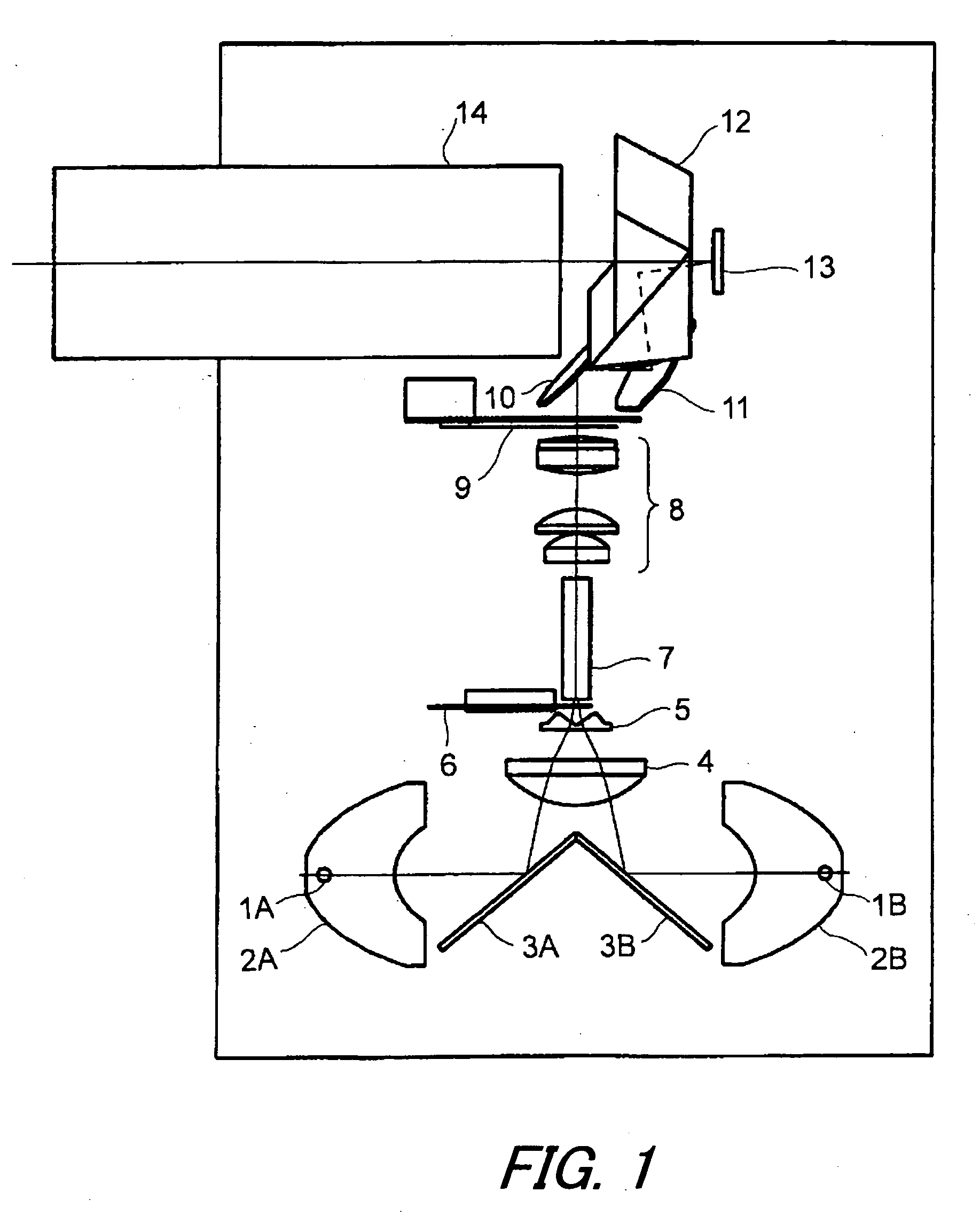
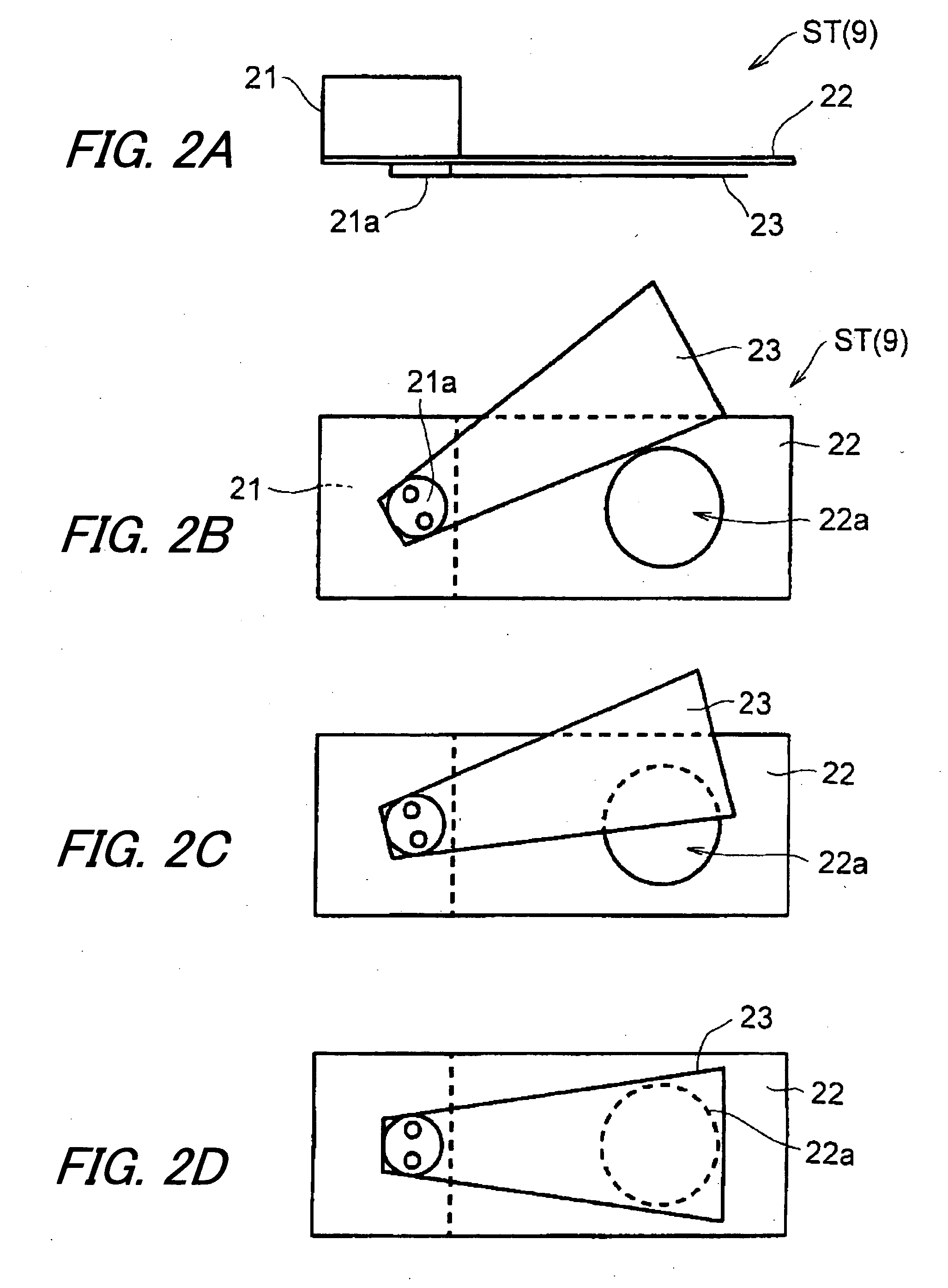
[0023]FIG. 1 illustrates a view from above of an embodiment of an image projecting apparatus having a variable stop in an illumination system. In FIG. 1, reference signs 1A and 1B denote light sources, reference signs 2A and 2B denote lamp reflectors, reference signs 3A and 3B denote folding mirrors, reference sign 4 denotes a condenser lens, reference sign 5 denotes a deflection prism, reference sign 6 denotes a color wheel, reference sign 7 denotes a rod integrator, reference sign 8 denotes a relay optical system, reference sign 9 denotes a variable stop mechanism, reference signs 10 and11 denote mirrors, reference sign 12 denotes a prism...


PUM


Abstract

An image projecting apparatus has an integrator for generating plural secondary-light-source images for generating illumination light with a uniform intensity; and a variable stop mechanism arranged at or near a position conjugate with the secondary-light-source images. The variable stop mechanism has a base plate having a fixed aperture; and a stop blade which moves across the aperture for changing a quantity of light. The change in the quantity of light passing through said variable stop caused by the movement of said stop blade is greater than a change in a size of an effective region of a stop aperture.

Description

[0001] This application is based on the application No. 2005-273814 filed in Japan Sep. 21, 2005, the entire content of which is hereby incorporated by reference. BACKGROUND OF THE INVENTION [0002] 1. Field of the Invention [0003] The present invention relates to an image projecting apparatus having a variable stop and, for example, relates to an image projecting apparatus having a variable stop for dynamically changing quantity of projected light according to brightness of displayed images. [0004] 2. Description of the Related Art [0005] U.S. Pat. No. 6,648,476 B2 ('476) suggests an image projecting apparatus for projecting an image on a display device onto a screen surface in an enlarged manner, wherein the image projecting apparatus changes the quantity of projected light through a variable stop. The image projecting apparatus adjusts a size of an effective diameter of light bundles through the variable stop for switching an image mode according to brightness and darkness of an a...

Claims


Application Information

Patent Timeline
IPC IPC(8): G03B21/14
CPCG03B9/04G03B9/06G03B33/08G03B21/2053G03B21/208H04N9/3155
Inventor SAWAI, YASUMASA
Owner KONICA MINOLTA OPTO
Why Eureka
Try Eureka