

Heat dissipating system and method
- Summary
- Abstract
- Description
- Claims
- Application Information
AI Technical Summary
Benefits of technology
Problems solved by technology
Method used
Image

Examples
Embodiment Construction
[0022] The present invention will be apparent from the following detailed description, which proceeds with reference to the accompanying drawings, wherein the same references relate to the same elements.
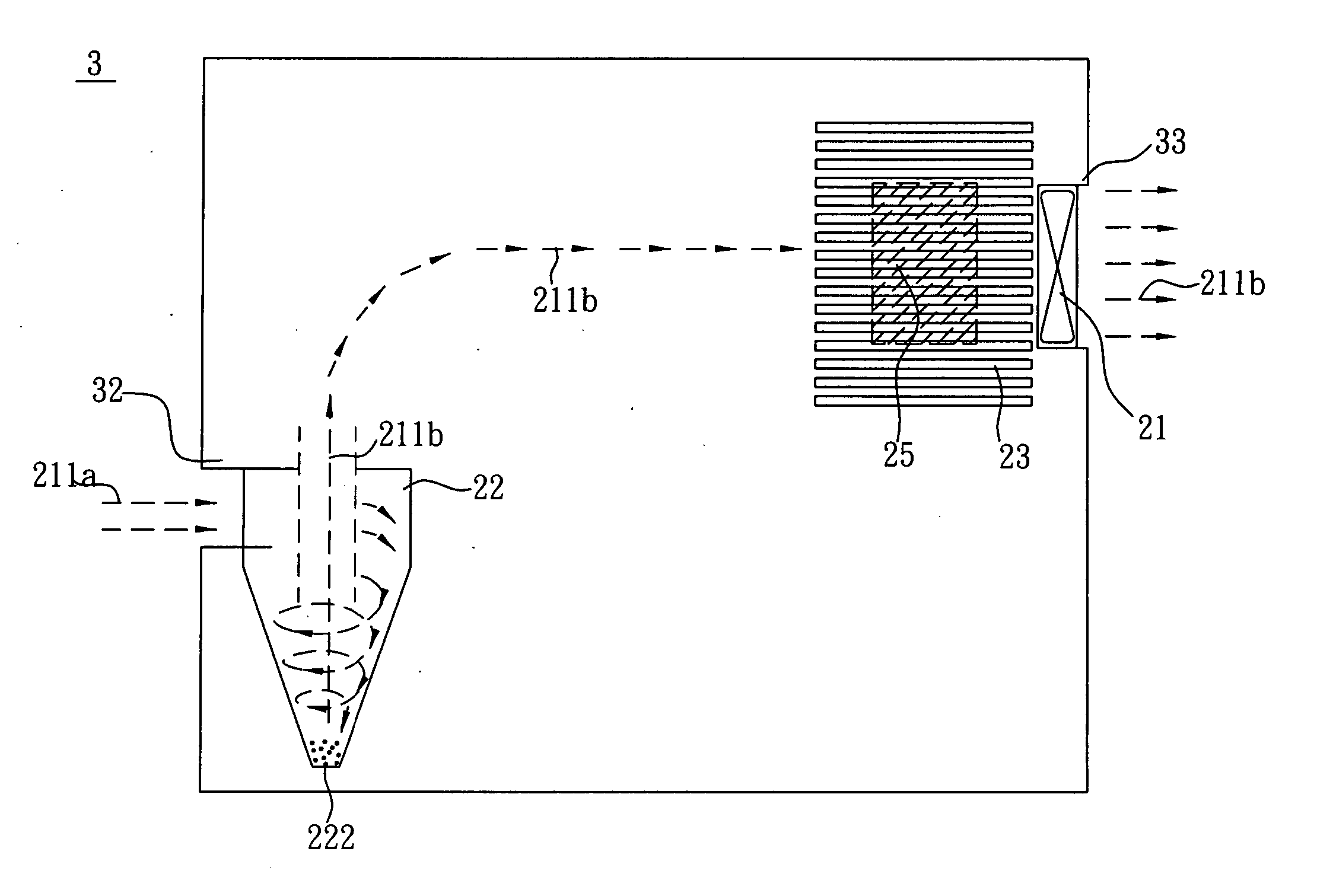
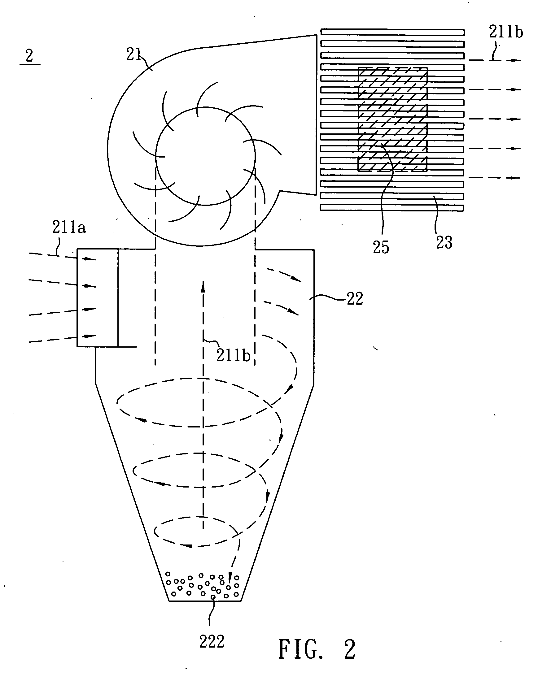
[0023]FIG. 2 is a schematic view showing a heat dissipating system according to a preferred embodiment of the invention. With reference to FIG. 2, a heat dissipating system 2, which is applied to a heat source 25, includes a fan 21, a dust-separating apparatus 22 and a heat sink 23.
[0024] In the embodiment, the fan 21 is an axial-flow fan or a centrifugal fan. When the fan 21 rotates, it can collect air from the exterior of the heat dissipating system 2 to generate an airflow 211a. Then, the airflow 211a flows into the dust-separating apparatus 22. Based on the centrifugal force and gravity force, the dusts 222 carried by the airflow 211a will be settled down to the bottom of the dust-separating apparatus 22. The separated airflow 211b is clean and enters the fan 21 directly. After...
PUM
 Abstract
Description
Claims
Application Information