
Methods and apparatus for reconstructing the anulus fibrosus

Inactive Publication Date: 2007-03-22
ANOVA
View PDF21 Cites 85 Cited by
  • Summary
  • Abstract
  • Description
  • Claims
  • Application Information

AI Technical Summary

Benefits of technology

[0016] The invention broadly facilitates reconstruction of the anulus fibrosus (AF) and the nucleus pulposus (NP). Such reconstruction prevents recurrent herniation following microlumbar discectomy. The invention may also be used in the treatment of herniated discs, annular tears of the disc, or disc degeneration, while enabling surgeons to preserve the contained nucleus pulposus. The methods and apparatus may be used to treat discs throughout the spine including the cervical, thoracic, and lumbar spines of humans and animals.
[0017] The invention also enables surgeons to reconstruct the anulus fibrosus and replace or augment the nucleus pulposus. Novel nucleus replacements (NR) may be added to the disc. Annulus reconstruction prevents extrusion of the nucleus replacements through holes in the anulus fibrosus. The nucleus replacements and the anulus fibrosus reconstruction prevent excessive pressure on the anulus fibrosus that may cause back or leg pain. The nucleus replacements may be made of natural or synthetic materials.
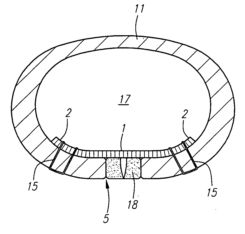
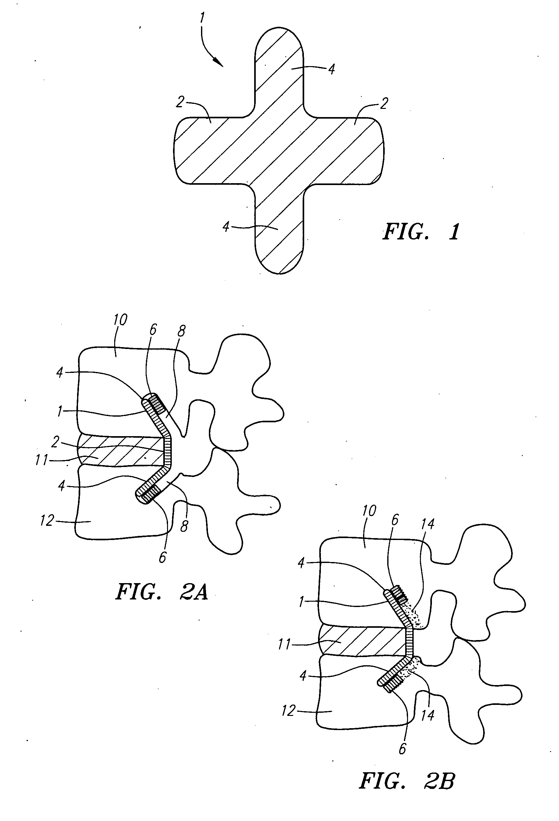
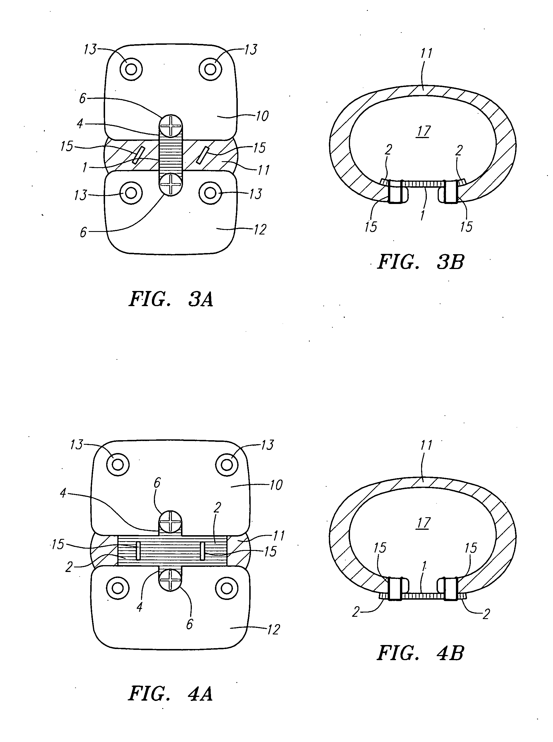
[0019] In the preferred embodiment, a spinal repair system according to the invention comprises a first end portion adapted for placement within an intervertebral body, a second end portion adapted for placement within an adjacent intervertebral body, and a bridge portion connecting the first and second end portions, the bridge portion being adapted to span a portion of an intervertebral disc space and prevent excessive outward bulging.
[0034] In the preferred embodiments, surgical mesh devices are placed between the anulus fibrosus and the posterior longitudinal ligament (PLL), or between the posterior longitudinal ligament and the periosteum that lies over the vertebrae, or both. The device and the location of the device optimize tissue ingrowth into the device yet minimize the risk of adhesions between the device and the nerves within the spinal canal.
[0035] The device is placed over the outside of the anulus fibrosus, the portion of the anulus fibrosus with the highest healing potential. The device is placed anterior to the PLL and / or periosteum to prevent tissue (adhesions) from forming between the disc and the nerves. The PLL also prevents the device from eroding into the nerves.

Problems solved by technology

The nucleus becomes thinner and less able to handle compression loads.
The redundant annular fibers are less effective in controlling vertebral motion.
Current surgical treatments for disc degeneration are destructive.
The first two groups of procedures compromise the treated disc.
Fusion procedures transmit additional stress to the adjacent discs, which results in premature disc degeneration of the adjacent discs.
These destructive procedures lead to acceleration of disc degeneration.
Current nucleus replacements (NRs) may cause lower back pain if too much pressure is applied to the anulus fibrosus.
Compressed nerves cause back and leg or arm pain.
The opening in the anulus fibrosus is enlarged during surgery, further weakening the anulus fibrosus.
Although microlumbar discectomy decreases or eliminates a patient's leg or arm pain, the procedure damages weakened discs.

Method used


Image

  • Methods and apparatus for reconstructing the anulus fibrosus
  • Methods and apparatus for reconstructing the anulus fibrosus
  • Methods and apparatus for reconstructing the anulus fibrosus

Examples


Embodiment Construction

Anatomy

[0100]FIG. 25A is a posterior view of a sagittal cross-section through a portion of the lumbar spine. The drawing shows bisected pedicles 202, 204, 206 of three lumbar vertebrae. Posterior longitudinal ligament (PLL) 210 courses over the middle of the vertebrae and fans out over the posterior portions 112, 114, 116 of the intervertebral discs. FIG. 25B is a sagittal cross section of two lumbar vertebrae and their associated ligaments. Posterior longitudinal ligament (PLL) 210 can be seen covering the posterior side of the intervertebral disc. It lies between the discs and the thecal sac and exiting nerves. The thecal sac also contains spinal nerves. Posterior longitudinal ligament (PLL) 210 is loosely attached to the anulus fibrosus of the discs and likely contributes cells that grow into devices placed adjacent to itself. Posterior longitudinal ligament (PLL) 210 also prevents adhesions between the thecal sac / nerves and any device that is placed between posterior longitudi...


PUM


Abstract

Methods and devices for fixing a defect in the anulus fibrosus of a patient. The devices include first and second vertical components extending from the middle region of the horizontal component, each of the first and second vertical components having a width and an end. The middle region of the horizontal component of the device blocks the defect in the anulus fibrosus. The first vertical component is attached to the upper vertebra and the second vertical component is attached to the lower vertebra. The horizontal component can be positioned beneath a layer of the posterior longitudinal ligament.

Description

[0001] This is a continuation-in-part of U.S. application Ser. No. 11 / 514,506, filed Nov. 1, 2005, which claims the benefit of U.S. Provisional Patent Application Ser. No. 60 / 713,969, filed Sep. 2, 2005. This also claims the benefit of U.S. Provisional Patent Application Ser. No. 60 / 738,833, filed Nov. 21, 2005. All of the above-referenced applications are hereby expressly incorporated by reference herein in their entirety. REFERENCE TO RELATED APPLICATIONS [0002] This application is also related to U.S. application Ser. No. 11 / 187,250, filed Jul. 22, 2005, which claims priority from U.S. Provisional Patent Application Ser. No. 60 / 590,942, filed Jul. 23, 2004. [0003] U.S. patent application Ser. No. 11 / 187,250 is a continuation-in-part of U.S. patent application Ser. No. 10 / 120,763, filed Apr. 11, 2002, which is a continuation-in-part of U.S. patent application Ser. No. 09 / 807,820, filed Apr. 19, 2001, now abandoned, which is a U.S. national phase application of PCT / US00 / 14708, file...

Claims


Application Information

Patent Timeline
IPC IPC(8): A61F2/44A61B17/80
CPCA61B17/0642A61F2250/0098A61B2017/0409A61B2017/044A61B2017/0648A61F2/442A61F2/4611A61F2002/2835A61F2002/30028A61F2002/3008A61F2002/30179A61F2002/30443A61F2002/30459A61F2002/30461A61F2002/30578A61F2002/30583A61F2002/3092A61F2002/30932A61F2002/30971A61F2002/4435A61F2002/4631A61F2210/0085A61F2220/0041A61F2220/0066A61F2220/0075A61F2230/0058A61F2250/0051A61B2017/0404A61F2002/30433
Inventor FERREE, BRET A.
Owner ANOVA
Learn More