Computer system and I/O bridge

a computer system and bridge technology, applied in the field of virtual computer systems, can solve the problems of increasing the overhead of the host os, increasing the complexity of the operation, increasing the operation cost, etc., and achieve the effect of reducing the overhead of the i/o access

Inactive Publication Date: 2007-03-22
HITACHI LTD
View PDF22 Cites 127 Cited by
  • Summary
  • Abstract
  • Description
  • Claims
  • Application Information

AI Technical Summary

Benefits of technology

[0015] Further, when the I / O is shared between the logical partitions at the hardware level of the I / O bridge, a software for identifying the logical partitions becomes unnecessary, thereby making it possible to reduce the overhead of the I / O access for the purpose of conducting high speed operation.

Problems solved by technology

In recent years, an increase in the number of servers makes the complexity associated with the operation increase, as a result of which there arises a problem of an increase in the operation costs.
Therefore, there arises such a problem that the processing of the host OS becomes overhead, and a response of the I / O is lowered.
However, because the special I / O device is required, there arise such problems that the manufacturing costs are high, and the versatility is low.
On the other hand, in the case where the I / O switch such as the advanced switching is used in the above conventional hypervisor to share the I / O device between the logical partitions, there occurs the following problems.
Because the above advanced switching (hereinafter referred to simply as “AS”) is capable of identifying nothing other than a physical node (or device), the AS is incapable of identifying the logical partitions that are provided by the hypervisor, and the AS as it is cannot be applied to the above hypervisor.
For that reason, software that centrally controls the I / O operation of the AS is required as in the above VMware, which leads such a problem that the processing of the software operation itself becomes the overhead of the I / O access.

Method used


Image

  • Computer system and I/O bridge
  • Computer system and I/O bridge
  • Computer system and I/O bridge

Examples


first embodiment

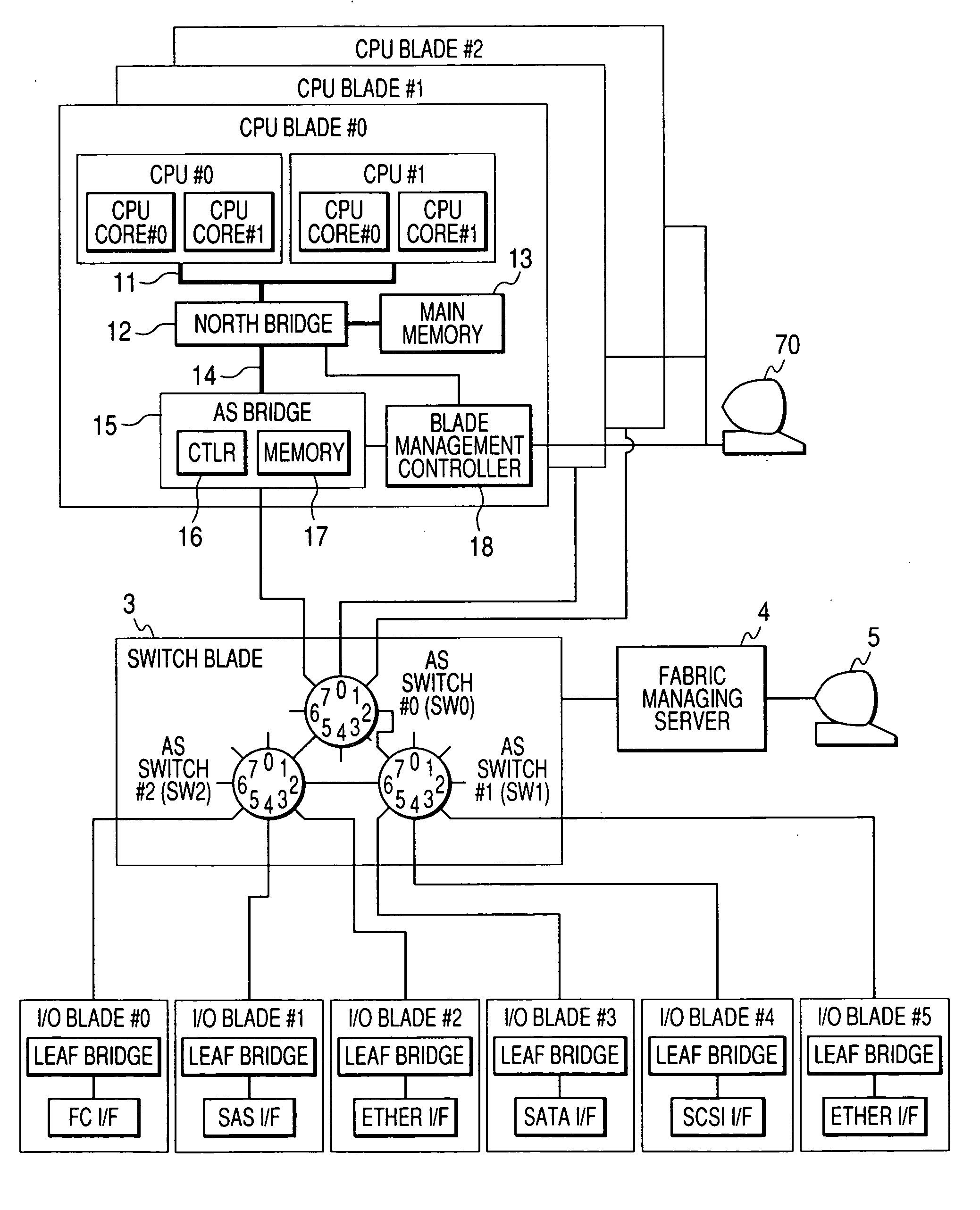
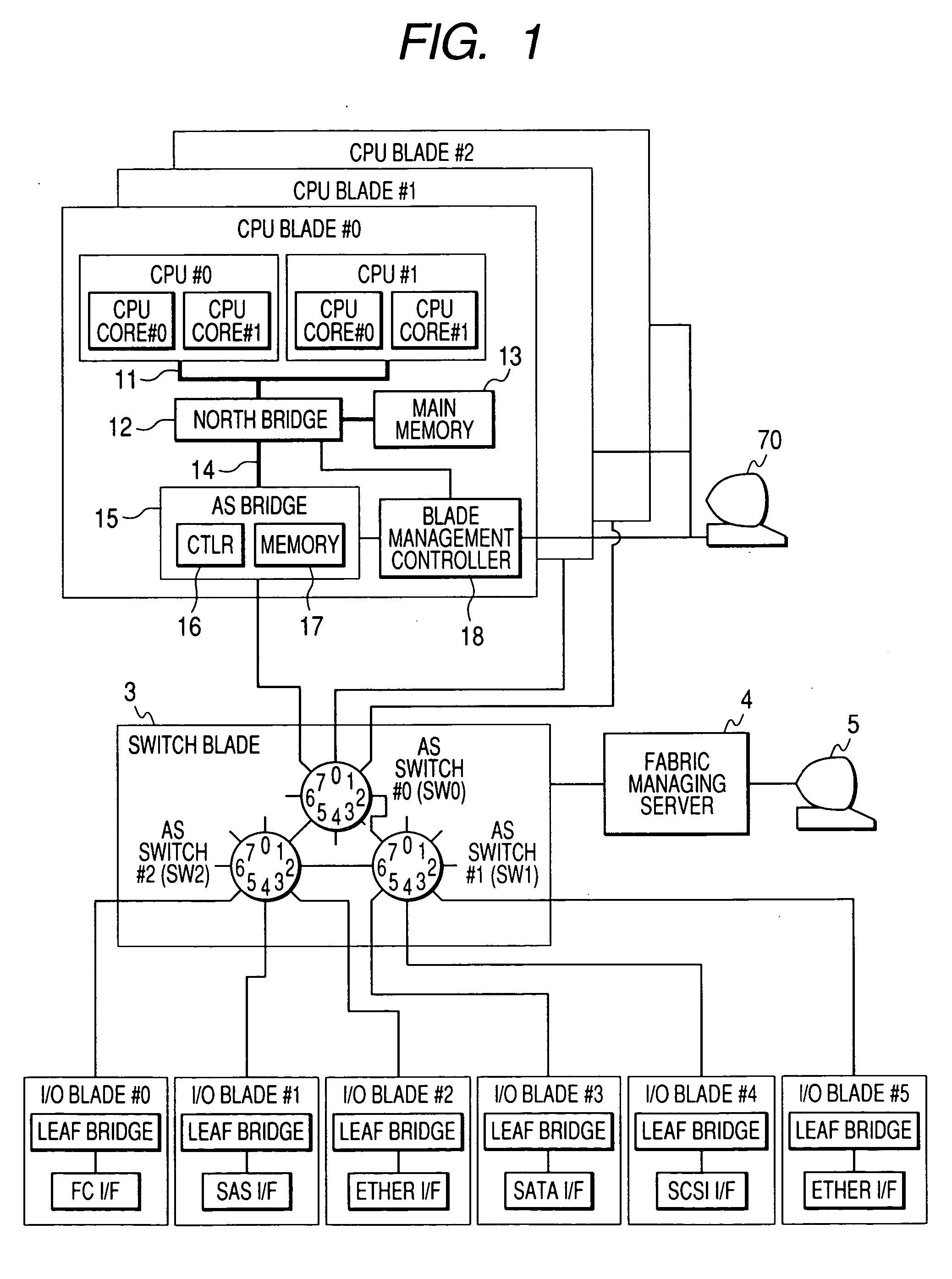
[0037]FIG. 1 is a block diagram showing a blade server system (physical computer) according to the present invention.

[0038] A blade server system includes plural CPU blades #0 to #2, plural I / O blades (or I / O cards) having various I / O interfaces, and a switch blade 3 having plural I / O switches #0 to #2 that connect the CPU blades #0 to #2 to the I / O blades #0 to #5. The CPU blades #0 to #2, the I / O blades #0 to #5, and the switch blade 3 are housed in a package not shown. The switch blade 3 is connected with a fabric managing server 4 that manages the allocation of the I / O blades #0 to #5 to the I / O switches #0 to #2 and the CPU blades #0 to #2. The fabric managing server 4 is connected with a console 5 that enables an input or an output with respect to a manager. The CPU blades (CPU modules) #0 to #2, the I / O blades (I / O modules) #0 to #5, and the switch blade (switch module) 3 are connected to each other through a backplane not shown.

[0039] In the blade server system according to...


PUM


Abstract

A computer system reduces an overhead by using an I/O switch high in versatility when realizing the sharing of an I/O between virtual computers. The system includes a CPU module #0 having plural CPU cores, an AS bridge 15 connected to the CPU cores, and a main memory that can be accessed from the CPU cores or the AS bridge 15, and AS switches SW0 and SW1 that connect the AS bridge 15 of the CPU module #0 and an I/O blade #5. The CPU module #0 has a hypervisor that divides the plural CPU cores and the main memory into plural logical partitions, and the AS bridge 15 adds virtual path information set in each of the logical partitions and path information of from the AS bridge 15 to the I/O blade #5 to the path information of the AS packet to switch over the AS packet between each of the logical partitions and the I/O blade #5 when relaying the AS packet transmitted or received between the logical partitions and the I/O blade #5.

Description

CLAIM OF PRIORITY [0001] The present application claims priority from Japanese application JP 2005-273400 filed on Sep. 21, 2005, the content of which is hereby incorporated by reference into this application. FIELD OF THE INVENTION [0002] The present invention relates to a virtual computer system, and more particularly to a technique by which the allocation of plural logical partitions and an I / O device are realized by an I / O switch. BACKGROUND OF THE INVENTION [0003] In recent years, an increase in the number of servers makes the complexity associated with the operation increase, as a result of which there arises a problem of an increase in the operation costs. As a technique that reduces the operation costs, attention is focused on a server consolidation that consolidates plural servers into one. [0004] As one of techniques that realize the server consolidations, there has been known a virtual machine that logically divides one computing machine at an arbitrary rate. In the techn...

Claims


Application Information

Patent Timeline
Patent Type & Authority Applications(United States)
IPC IPC(8): G06F15/173
CPCG06F13/4027
Inventor TARUI, TOSHIAKIYASUDA, YOSHIKO
Owner HITACHI LTD
Why Eureka
Try Eureka