Heat pump

a heat pump and heat exchange technology, applied in the field of heat pumps, can solve the problems of not being able to perform smooth operation, unable to vary the ratio between the displacement of the expander and the displacement of the compressor according to operation conditions, and performing smooth operation, so as to achieve smooth and efficient operation and improve the coefficient of performance.

Inactive Publication Date: 2007-03-29
PANASONIC CORP
View PDF9 Cites 58 Cited by
  • Summary
  • Abstract
  • Description
  • Claims
  • Application Information

AI Technical Summary

Benefits of technology

[0021] Further, in the heat pump of the present invention, the control device executes a first controlling in which, when the difference between a high pressure PH of the refrigerant circulating in the circulation passage and a predetermined value PHT determined based on a value at which the coefficient of performance of the heat pump is optimized is outside a predetermined range PHDR, the opening of the second throttling device is varied so that the absolute value of the difference between the pressure PH and the predetermined value PHT becomes smaller. After completing the first controlling, the control device executes a second controlling in which, when the difference between a degree of superheat SH of the refrigerant flowing into the compressor and a

Problems solved by technology

Because of its structure, the expander cannot recover energy unless the refrigerant passes through it in a predetermined direction.
In the heat pump in which the expander and the compressor are directly coupled, the expander and the compressor operate at the same rotational speed and therefore it is impossible to vary the ratio between the displacement of the expander and the displacement of the compressor according to operation condit

Method used


Image

  • Heat pump
  • Heat pump
  • Heat pump

Examples


Embodiment Construction

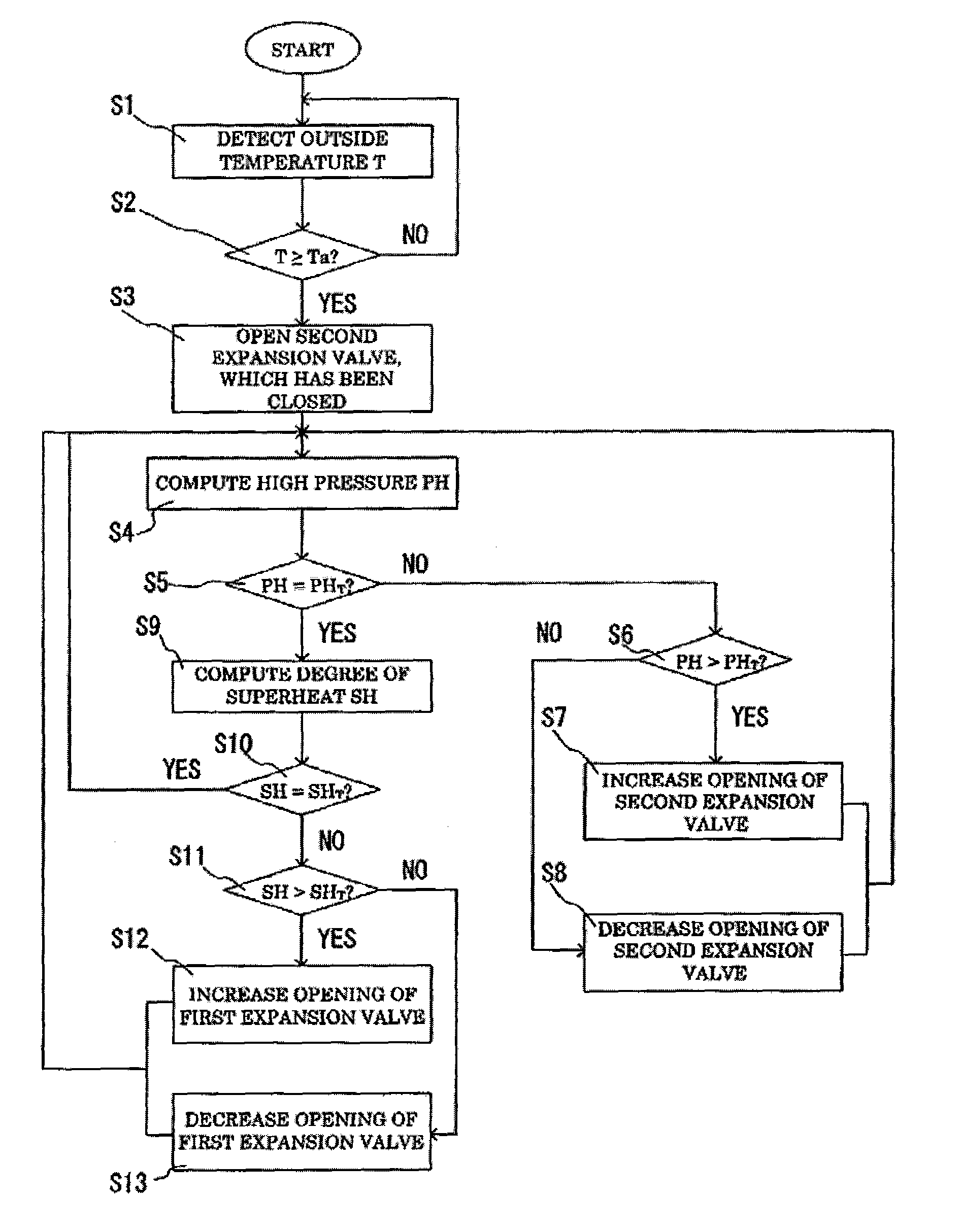
[0038] Hereinbelow, preferred embodiments of the present invention are described with reference to the drawings. In the following description, the same components and steps may be designated with the same reference numerals to avoid repetitive description.

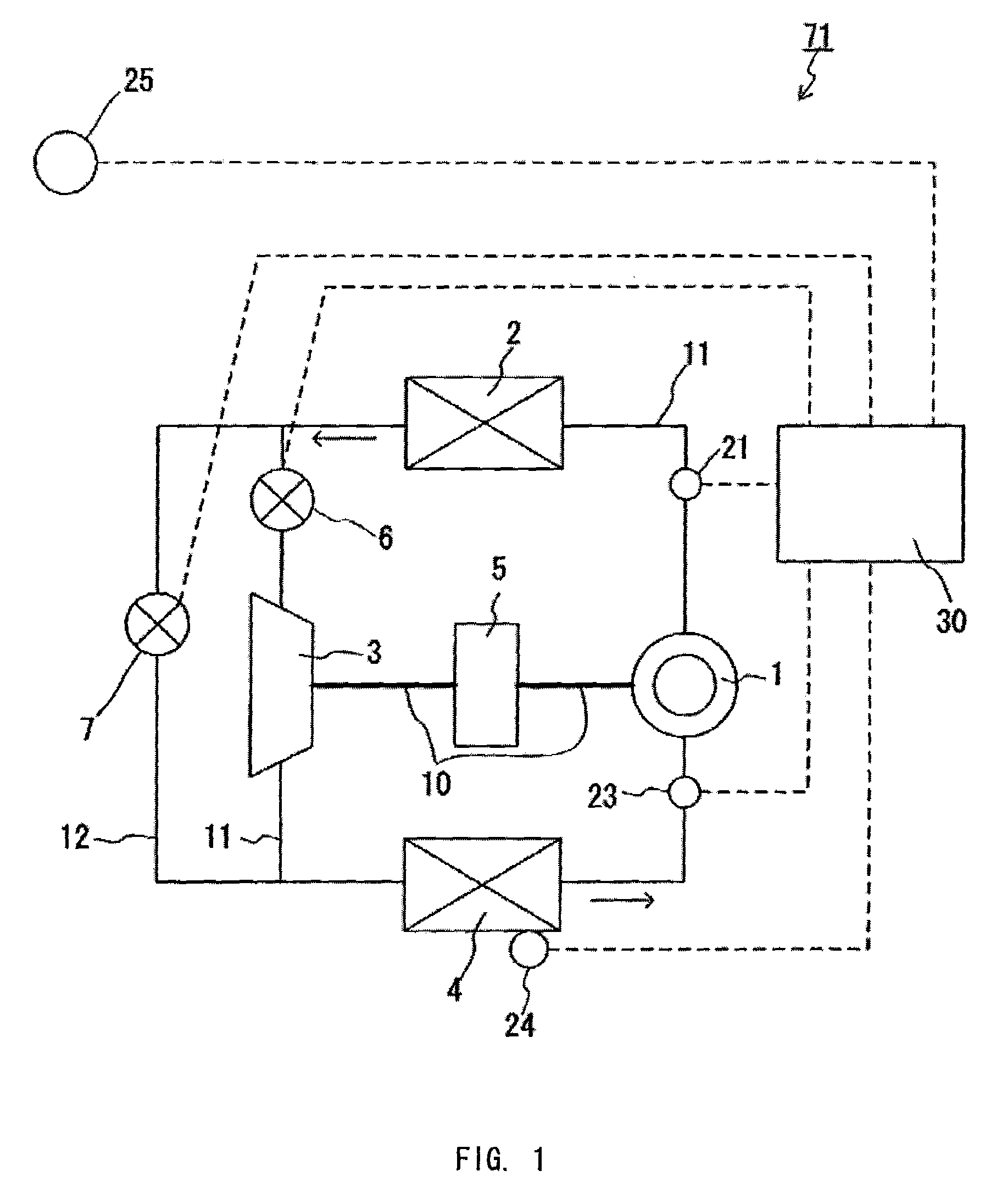
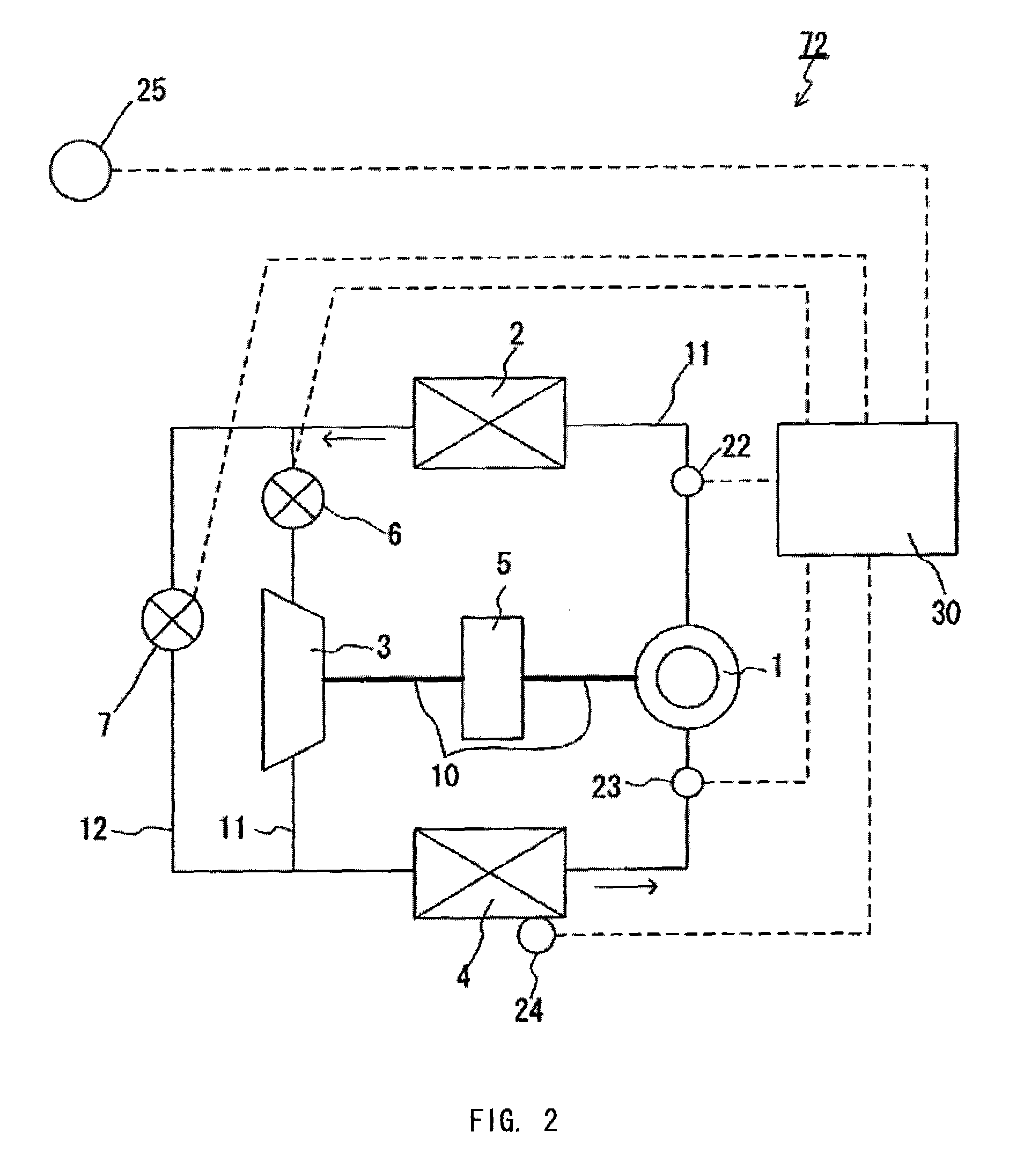
[0039]FIG. 1 illustrates a configuration diagram of one embodiment of the heat pump according to the present invention. This heat pump 71 is provided with a compressor 1, a radiator 2, an expander 3, and an evaporator 4, as the primary constituent components for carrying out the fundamental functions of a heat pump. These components are connected by a piping 11 that forms a circulation passage in which refrigerant circulates through the compressor 1, the radiator 2, the expander 3, and the evaporator 4, in that order. One end of a piping 12 is connected to the piping 11 between the radiator 2 and the expander 3, while the other end thereof is connected to the piping 11 between the expander 3 and the evaporator 4. The piping 12 for...


PUM


Abstract

A heat pump of the present invention has a compressor and an expander coupled with a common axis of rotation, a first throttling device disposed in a circulation passage of refrigerant, and a second throttling device disposed in a bypass passage diverted from the expander. A control device controls the openings of these throttling devices. The control device executes a first controlling in which the opening of the first throttling device is adjusted in order to bring a high pressure PH in a refrigeration cycle close to a predetermined value determined based on a value at which the coefficient of performance (COP) of the heat pump is optimized, and after the first controlling is completed, it executes a second controlling in which the opening of the second throttling device is adjusted in order to bring a degree of superheat SH close to a predetermined positive value. This ensures smooth and stable operations of the heat pump.

Description

[0001] This application is a continuation of prior pending International Application Number PCT / JP2005 / 022655, filed on Dec. 9, 2005, which designated the United States.BACKGROUND OF THE INVENTION [0002] 1. Field of the Invention [0003] The present invention relates to heat pumps useful for hot water heaters, air-conditioners, and the like, and more particularly to a heat pump furnished with a mechanism for recovering energy with an expander. [0004] 2. Description of the Related Art [0005] A heat pump employing an expander in place of an expansion valve can recover the expansion energy of refrigerant as electric power or mechanical power. As the expander, in many cases a positive displacement expander is used that has a space with a variable capacity for introducing and expanding the refrigerant therein. The energy recovery with the expander has a significant value, particularly in the transcritical cycle of carbon dioxide in which the high pressure reaches a supercritical state of ...

Claims


Application Information

Patent Timeline
IPC IPC(8): F25B13/00F25B41/04
CPCF25B9/008F25B2700/21152F25B13/00F25B41/062F25B49/02F25B2309/061F25B2313/0314F25B2341/066F25B2400/0411F25B2400/14F25B2500/19F25B2600/17F25B2600/2501F25B2600/2513F25B2700/1931F25B2700/2106F25B2700/21151F25B9/06F25B41/385F25B41/39F25B41/34Y02B30/70
Inventor HONMA, MASAYAYAKUMARU, YUUICHITAMURA, TOMOICHIROSAITO, TETSUYA
Owner PANASONIC CORP
Why Eureka
Try Eureka