Gas fireplace monitoring and control system

a technology for monitoring and controlling systems and gas fireplaces, applied in the direction of gaseous heating fuel, stoves or ranges, ways, etc., can solve problems such as safety and maintenance problems

Inactive Publication Date: 2007-03-29
HNI TECH INC
View PDF28 Cites 61 Cited by
  • Summary
  • Abstract
  • Description
  • Claims
  • Application Information

AI Technical Summary

Benefits of technology

[0008] One aspect of the invention relates to a monitoring and control system for use with a heating appliance. The heating appliance includes a burner, a gas valve configured to control fuel flow to the burner, and an ignition system configured to ignite a flame at the burner. The system includes a sensor module, a computer system, a controller, and a communication system. The sensor module is configured to monitor the burner, gas valve, and ignition system and generate monitoring signals. The controller is configured to generate fault condition signals based on the monitoring signals. The communication system is configured to communicate the fault condition signals to the computer system, wherein the computer system is located remotely from the heating appliance. The computer system is configured to generate control signals in response to predetermined fault condition signals. The communication system is configured to communicate the control signals to the controller for control of at least one of the

Problems solved by technology

Providing a flame generated from gas can involve safety and

Method used


Image

  • Gas fireplace monitoring and control system
  • Gas fireplace monitoring and control system
  • Gas fireplace monitoring and control system

Examples


example 1

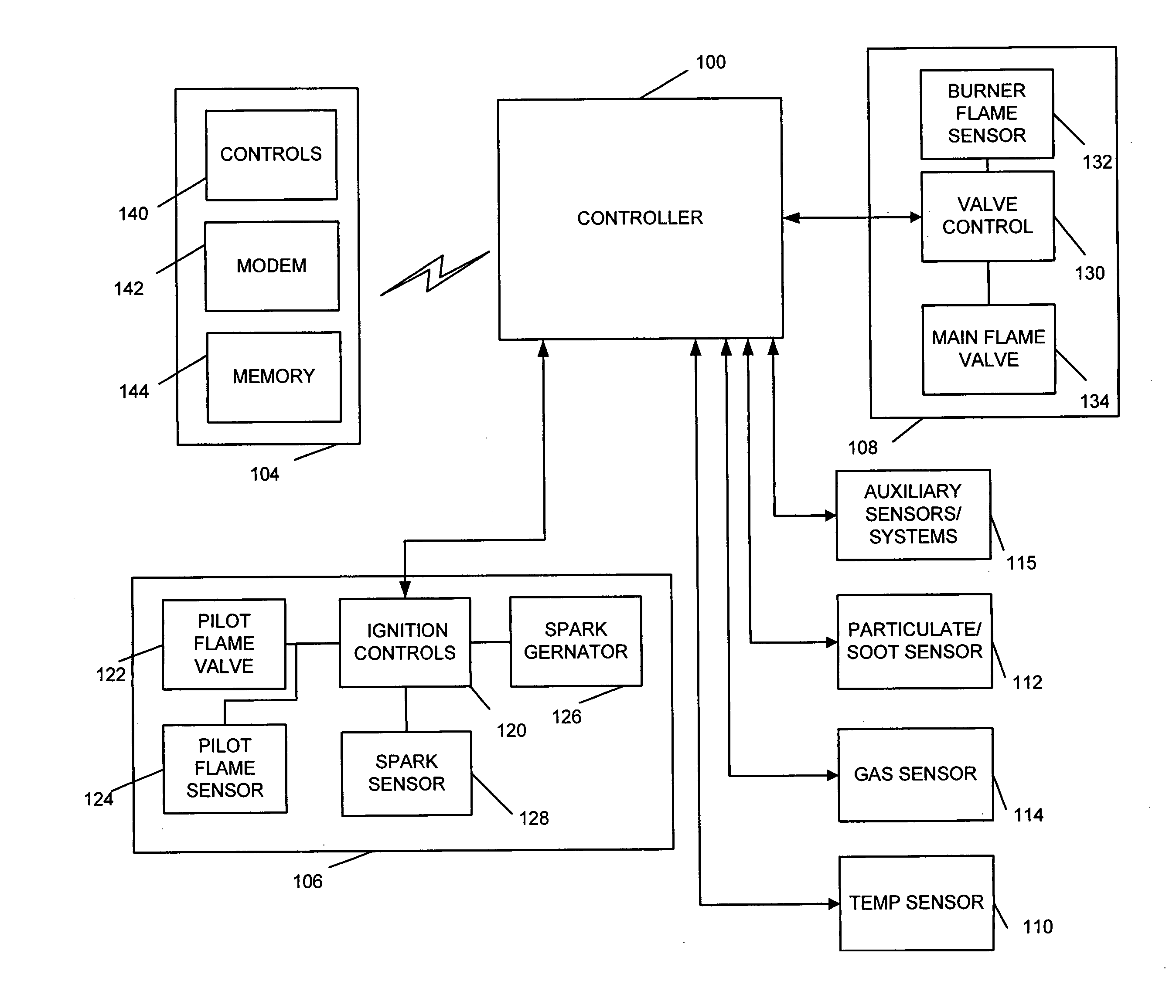
[0057] 1. A fault is tripped on the controller by the fireplace actions. [0058] 2. The controller checks the telephone line to see if it is being used, and if so waits a set amount of time after it is not used before dialing. [0059] 3. If / when the line is not in use, the controller performs any action necessary to reach an outside line. [0060] 4. The controller then dials the designated phone number to reach the remotely located computer system. [0061] 5. The receiving computer system picks up and waits for ready to send code from the fireplace controller. [0062] 6. The receiving computer system hears a “ready to send” code and transmits “ready to receive” code. [0063] 7. After hearing the ready to receive code, the fireplace controller sends the serial number with a coded signal indicating the fault code and other information about the fireplace. [0064] 8. When the transmission of information is completed, the fireplace controller will then wait until it hears the received successf...


PUM


Abstract

A monitoring and control system for use with a decorative heating appliance such as a fireplace, stove, or fireplace insert. The monitoring and control system includes a sensor module, a computer system, a controller, and a communication system. The sensor module is configured to monitor a burner, gas valve, and ignition system of the heating appliance and generate monitoring signals. The controller is configured to generate fault condition signals based on the monitoring signals. The communication system is configured to communicate the fault condition signals to the computer system, wherein the computer system is located remotely from a living space within which the heating appliance resides. The computer system is configured to generate control signals in response to predetermined fault condition signals and communicate those signals to the controller via the communication system for control of at least one of the burner, gas valve, and ignition system or other functions of the heating appliance.

Description

BACKGROUND OF THE INVENTION [0001] 1. Field of the Invention [0002] The present invention generally relates to monitoring and control systems, and more specifically relates to systems and methods for monitoring and control systems heating appliances such as fireplaces, stoves, and fireplace inserts. [0003] 2. Related Art [0004] Gas, electric, and wood burning heating appliances such as fireplaces, stoves and fireplace inserts are an efficient method for providing warmth and creating the appeal of a fire within a room. Fireplaces have become commonplace in today's building trades for both residential and commercial applications. Most new home construction designs include at least one, and often several fireplaces. Further, a significant number of remodeling projects are focused on fireplaces. [0005] Most known heating appliances include some type of heat control system that facilitates on / off control, the level of heat output, and possibly thermostatic control. In the case of a gas p...

Claims


Application Information

Patent Timeline
IPC IPC(8): F24B1/187
CPCF24C3/122F24B1/1808
Inventor BACHINSKY, THOMASWILLIAMS, KELLY
Owner HNI TECH INC
Why Eureka
Try Eureka