
Gas-biased hydraulic cylinder

a hydraulic cylinder and gas-biased technology, applied in the field of hydraulic cylinders, can solve the problems of not acting to compensate, '215 and '101 systems still suffer from being complicated, etc., and achieve the effect of increasing the volume of pressurized gas

Inactive Publication Date: 2007-03-29
FURGALA GEORGE WOJCIECH
View PDF18 Cites 35 Cited by
  • Summary
  • Abstract
  • Description
  • Claims
  • Application Information

AI Technical Summary

Benefits of technology

[0012] In another aspect, the hollow cylinder is fluidly connected to an external expansion tank providing an increased volume of pressurized gas.

Problems solved by technology

While the pressurized gas chamber does function as an accumulator in floatingly supporting the second piston, it does not act to compensate for the tare weight of the apparatus connected to the second piston (or the second piston itself), as hydraulic fluid is used to actuate the first piston, the second piston and whatever is attached to the second piston.
While providing useful energy storage systems, the '215 and '101 systems nevertheless suffer from being complicated, requiring a series of directional valves, relief valves, accumulators and the like.

Method used


Image

  • Gas-biased hydraulic cylinder
  • Gas-biased hydraulic cylinder
  • Gas-biased hydraulic cylinder

Examples


Embodiment Construction

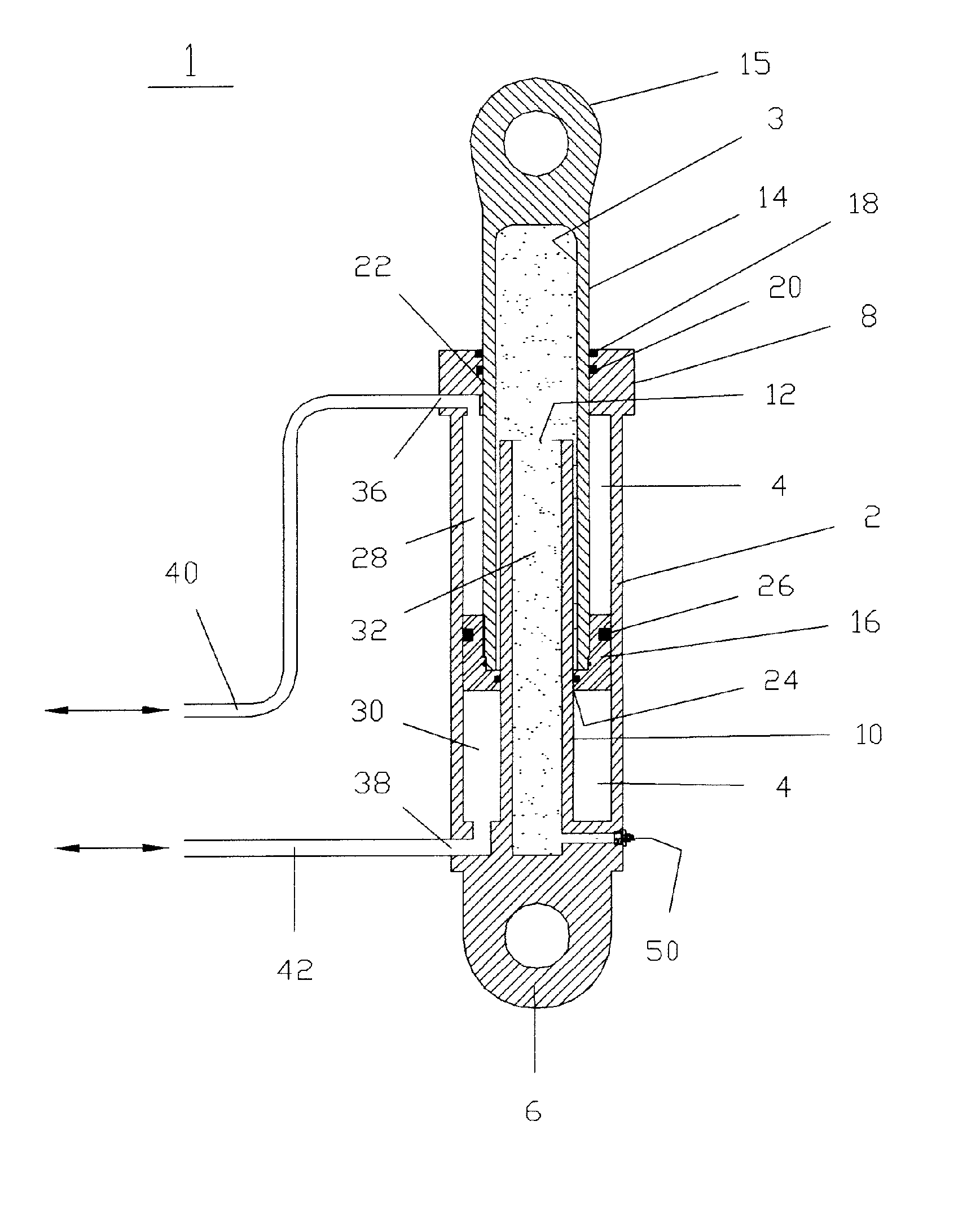
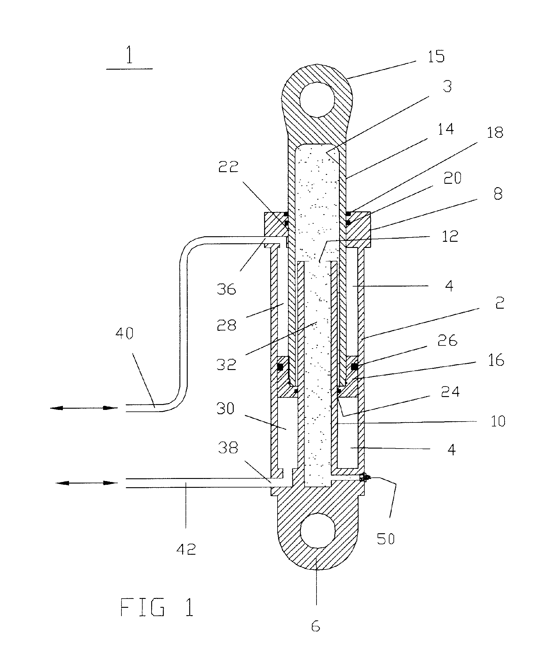
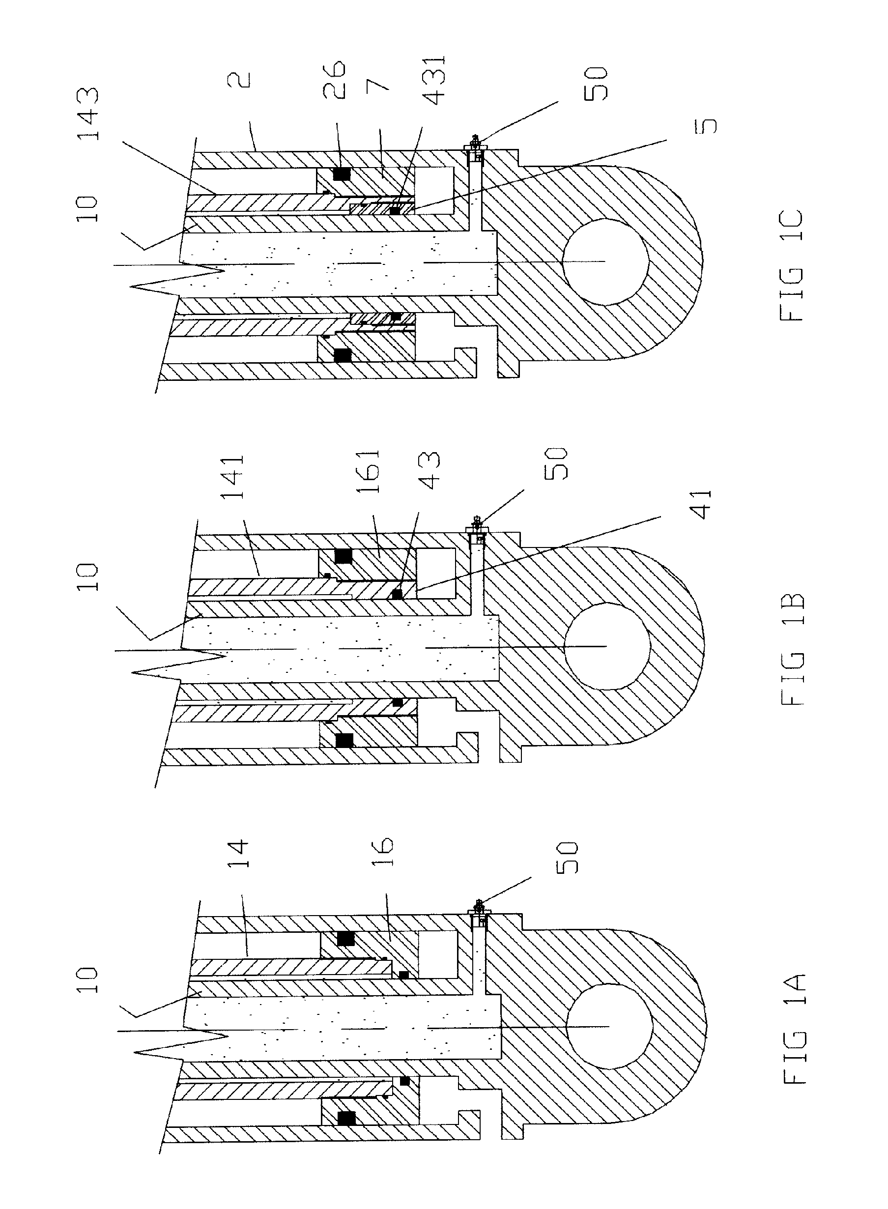
[0028] The preferred embodiment of a gas-biased hydraulic cylinder according to the invention generally referred to as reference numeral 1 is shown in FIG. 1. Referring to FIG. 1, it can be seen that the hydraulic cylinder 1 generally comprises a tubular body 2 defining a longitudinally disposed cylindrical chamber 4 bounded by a blind end 6 and a rod end cylinder head 8 as known in the art.

[0029] The rod end cylinder head 8 preferably has a wiper 18 and a seal 20 or any suitable sealing system known in the art. A longitudinally disposed cylindrical opening 22 passing through cylinder head 8 is substantially aligned with the longitudinally disposed cylindrical chamber 4. The blind end 6 is adapted to be connected to a fixed or movable object.

[0030] A reciprocable hollow cylinder rod 14 has a piston 16 mounted at a piston end and a connection end 15 at the other. The combination of the hollow cylinder rod 14 and piston 16 will be referred to hereafter as a piston assembly. Connecti...


PUM


Abstract

A gas-biased hydraulic cylinder for compensating for the tare weight of a material handling apparatus to be actuated by the cylinder. A tubular body is capped by a cylinder head and a blind end. A piston assembly comprising a hollow cylinder rod having a piston travels through the cylinder head, the piston being seated within the tubular body for reciprocating action therein. The piston is actuated by hydraulic fluid. A hollow cylinder projects from the blind end through an opening in the piston assembly and into the hollow cylinder rod, the hollow cylinder and the piston assembly being sealingly and slidably connected. The interiors of the hollow cylinder and hollow cylinder rod form an interior chamber that is pressurized with gas to bias the cylinder rod so as to compensate for the tare weight of the material handling apparatus.

Description

FIELD OF THE INVENTION [0001] The present invention relates to hydraulic cylinders and in particular to a hydraulic cylinder biased by a pressurized gas within the hydraulic cylinder. BACKGROUND OF THE INVENTION [0002] Hydraulic cylinders are used as actuators in a wide variety of applications, particularly in association with heavy construction equipment. A simple hydraulic cylinder comprises a cylinder tube body having blind (rear) and rod (front) ends and a cylindrical bore travelling from the rear to the front end defining a piston chamber. The blind and rod ends each have inlet-outlet ports for selectively feeding and discharging hydraulic fluid into the bore. A rod having an actuation end and a piston end is slidingly and sealingly mounted in an opening in the rod end and extends into the cylinder tube body through the opening. The piston end is slidably and sealingly mounted in the cylindrical bore. The selective feeding and discharging of hydraulic fluid into the bore on eit...

Claims


Application Information

Patent Timeline
IPC IPC(8): F16F9/43
CPCF15B1/024F15B15/1476F15B15/1466
Inventor FURGALA, GEORGE WOJCIECH
Owner FURGALA GEORGE WOJCIECH
Features
  • Generate Ideas
  • Intellectual Property
  • Life Sciences
  • Materials
  • Tech Scout
  • Unparalleled Data Quality
  • Higher Quality Content
  • 60% Fewer Hallucinations
Learn More