Information-processing device and information-processing system

a technology of information processing and information processing, applied in the field of information processing device and information processing system, can solve the problems of no conventional technique proposed to reduce the amount of calculation performed, and many kinds of practical problems to be solved, so as to avoid an increase in the number of bits

Inactive Publication Date: 2007-03-29
JAPAN SCI & TECH CORP +2
View PDF3 Cites 134 Cited by
  • Summary
  • Abstract
  • Description
  • Claims
  • Application Information

AI Technical Summary

Benefits of technology

[0025] In general, a fast Fourier-transformation consumes a considerable amount of time, and thus requires a considerable amount of calculation In the aforementioned mode, the total amount of calculation significantly depends on the amount of calculation using the evaluation function. Taking this condition into account, the information-processing device according to the present invention creates multiple levels of binned images having different resolutions and performs the calculation using the evaluation function on the binned images at each level, from the lowest to the highest resolution. Compared to other methods that do not use multiple levels of binned images, the present method reduces the number of normal or expanded pixel cells on which the calculation is to be performed. This leads to a remarkable decrease in the number of times to perform the fast Fourier-transformation to locate the reception point of the light emitted from the light source.
[0043] This system can correctly locate each transmitter device on the basis of the pilot signal and obtain identification information of the transmitter device. This information can serve as a key to retrieving various kinds of additional information to be used for identifying each transmitter device, discriminating plural transmitter devices or other purposes. Examples of the additional information include graphical icons for constructing a graphic user interface on which users can easily control each transmitter device through a corresponding icon displayed on the captured image.

Problems solved by technology

However, there are various kinds of practical problems to be solved in bringing the home network into popular use.
There is no conventional technique proposed to reduce the amount of calculation performed for the aforementioned purpose and improve the efficiency of determining the reception point of the ID light on the captured image.

Method used


Image

  • Information-processing device and information-processing system
  • Information-processing device and information-processing system
  • Information-processing device and information-processing system

Examples


example

[0150] This section describes the result of an experiment using a simplified, trial version of the “OPTO-NAVI” system developed by the present inventors and others.

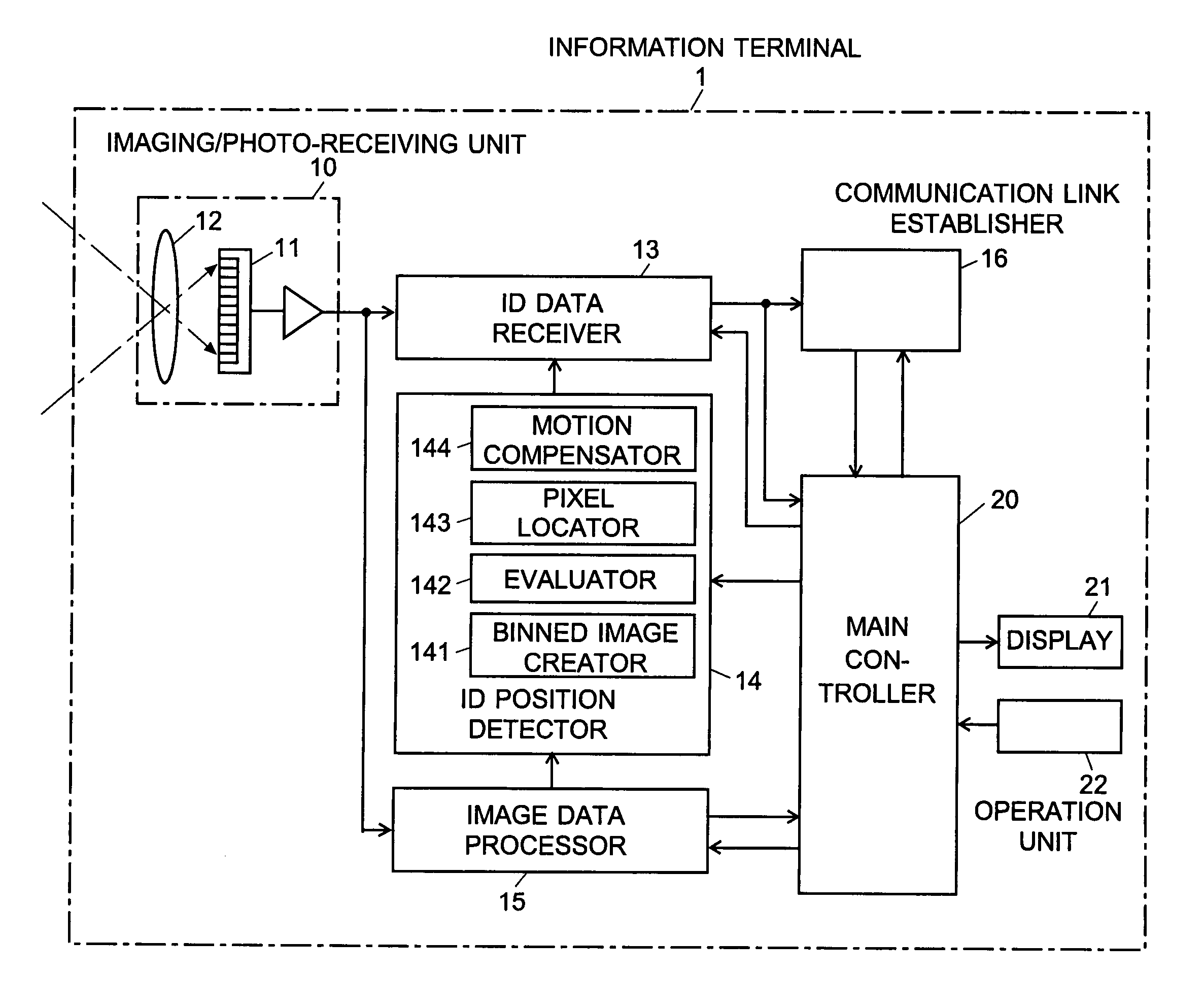
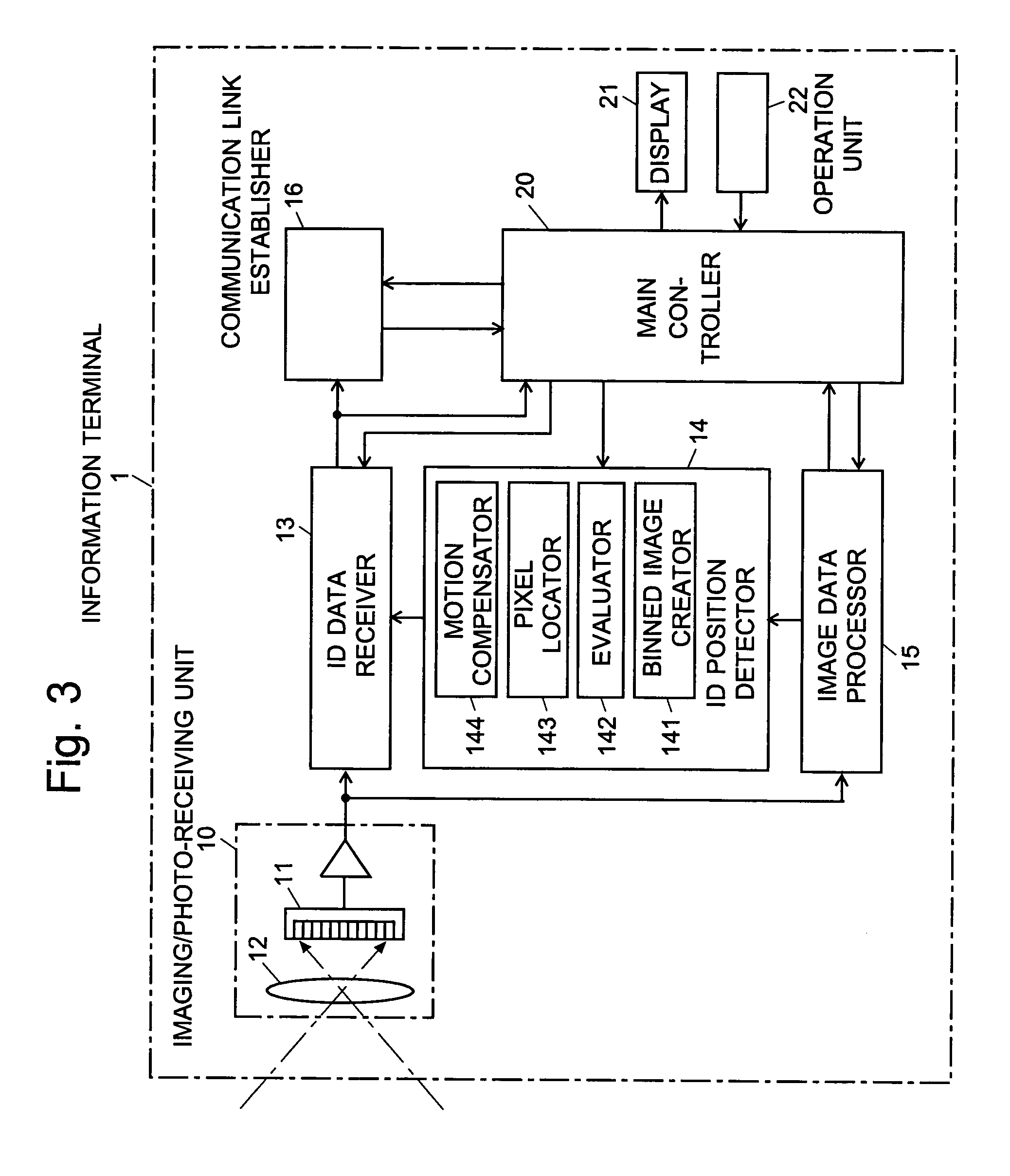
[0151] The trial system used the image sensor disclosed in Non-Patent Document 2 as the image sensor 11 in FIG. 3. This image sensor can simultaneously receive up to seven ID signals (i.e. nID=7) with a frame rate of 1.2 kfps per ID for capturing ID images from which the ID information is to be read out.

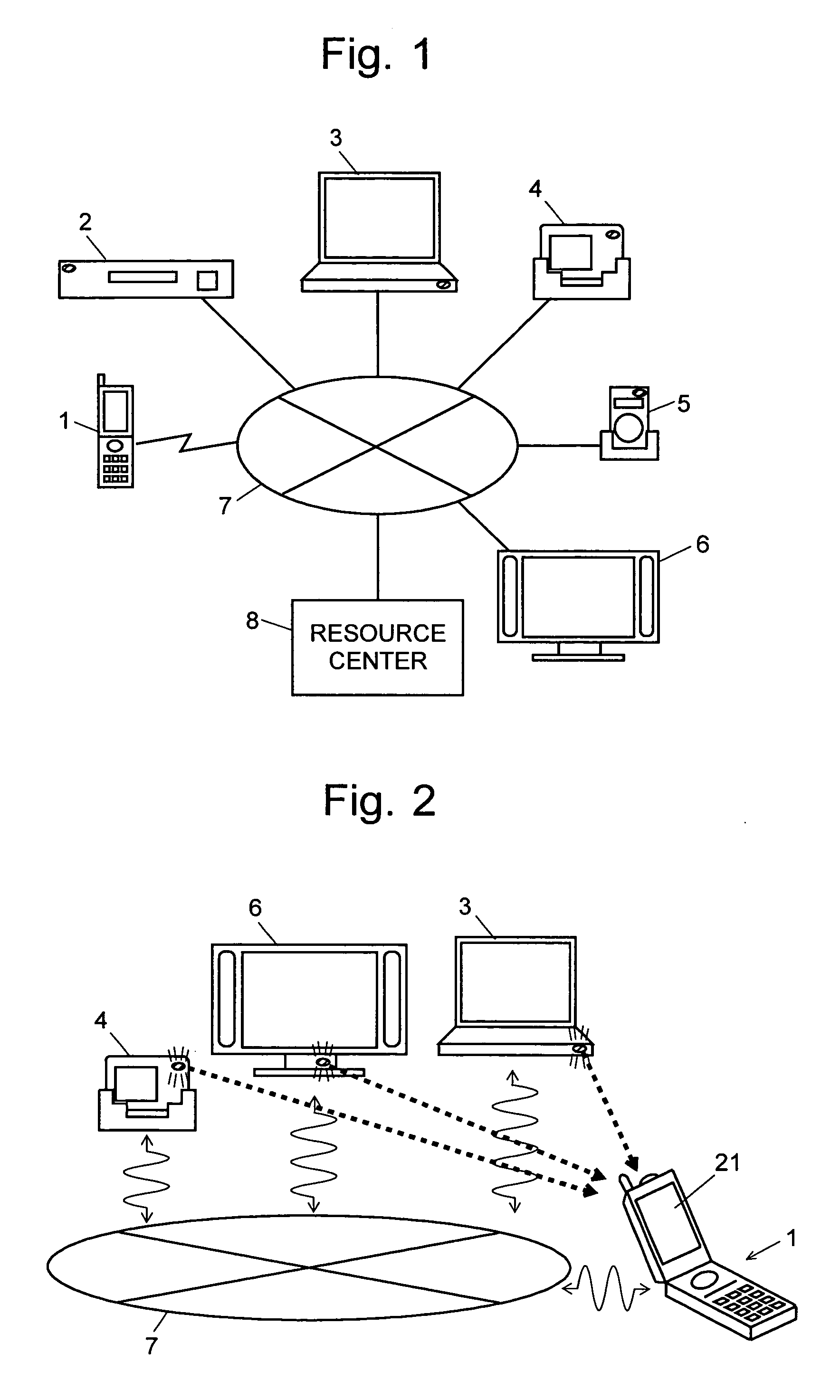
[0152] The system also included a camera, which substituted for the information terminal 1 of the remote control system shown in FIG. 2, and three ID transmission modules, which correspond to the information devices. Each transmission module had a red LED as the ID light source, which corresponds to the optical beacon of the information device. The purpose of using the visible light (i.e. red light) was to make the light source easy to handle in the experiment. In practical applications, however, it is desirable to use n...


PUM


Abstract

For an information terminal to be operated by users for collecting predetermined pieces of information from remote information devices by free-space optical communication, the present invention provides a technique for suppressing the power consumption of the information terminal by minimizing the amount of calculation performed to collect the aforementioned information. According to the present invention, each information device emits ID light on which a low-frequency pilot signal is superimposed. The information terminal captures a series of frames of images including the ID light and locates the ID light within the images by the following steps: (1) creating multiple levels of binned images having different resolutions for each frame of the image; (2) calculating an evaluation index for each pixel within a target range of the binned images at each level, from the lowest to the highest resolution, where the target range is narrowed every time the process switches over to a lower level. In (2), the evaluation index is calculated by an evaluation function including fast Fourier transformation performed throughout the series of frames of images. The evaluation index thus calculated is compared with a threshold to determine whether the pixel concerned is receiving ID light. The present technique significantly reduces the number of pixel to be analyzed and evaluated, thereby decreasing the total number of arithmetic operations to be performed using the evaluation function. Thus, the power consumption is suppressed.

Description

[0001] The present invention relates to an information-processing system that uses an information terminal operated by users to collect predetermined pieces of information from information devices located separately and remotely or to remotely control various types of information devices, in which at least a portion of the information concerned is transmitted by free-space optical communication. The present invention also relates to an information-processing device directly operated by the user in the aforementioned system. BACKGROUND OF THE INVENTION [0002] In recent years, personal computers have pervaded into people's domestic lives. Other types of digital information devices, such as digital television sets or digital versatile disc (DVD) recorders, are also becoming popular. Under such circumstances, many people are constructing home networks including the aforementioned information devices as their principal components. Meanwhile, refrigerators, microwave ovens and other home ...

Claims


Application Information

Patent Timeline
Patent Type & Authority Applications(United States)
IPC IPC(8): G06T1/00G06F17/00G01B11/00H04B10/11H04B10/112H04B10/118H04B10/524H04B10/54
CPCG06T1/00
Inventor KAGAWA, KEIICHIROOHTA, JUNMAEDA, YUKIMASAKI, YASUOTANABE, HIDEKIMIYAKE, YASUNARI
Owner JAPAN SCI & TECH CORP
Why Eureka
Try Eureka