
Methods for making micro-fluid ejection head structures

a technology of ejection head and nozzle, which is applied in the field of microfluid ejection devices, can solve the problems of requiring specialized equipment, affecting the precision of manufacturing parts that meet such demands, and requiring specialized equipment, so as to improve the quality of ejection head and improve the nozzle members. the effect of precise size and shape, improved ejection head structure and improved nozzle members

Inactive Publication Date: 2007-03-29
FUNAI ELECTRIC CO LTD
View PDF12 Cites 28 Cited by
  • Summary
  • Abstract
  • Description
  • Claims
  • Application Information

AI Technical Summary

Benefits of technology

[0002] Micro-fluid ejection heads are useful for ejecting a variety of fluids including inks, cooling fluids, pharmaceuticals, lubricants and the like. A widely used micro-fluid ejection head is in an ink jet printer. Ink jet printers continue to be improved as the technology for making the micro-fluid ejection heads continues to advance. New techniques are constantly being developed to provide low cost, highly reliable printers which approach the speed and quality of laser printers. An added benefit of ink jet printers is that color images can be produced at a fraction of the cost of laser printers with as good or better quality than laser printers. All of the foregoing benefits exhibited by ink jet printers have also increased the competitiveness of suppliers to provide comparable printers in a more cost efficient manner than their competitors.
[0010] An advantage of the embodiments described herein can include that they may provide an improved micro-fluid ejection head structures and, in particular, improved nozzle members for micro-fluid ejection heads. Another advantage can include that the methods may enable the formation of nozzles that have a precise size and shape in a nozzle member after the nozzle member has been attached to a micro-fluid ejection head structure. Other advantages of the embodiments described herein may include an ability to readily remove a material that enables such precise nozzles formation in the nozzle member.

Problems solved by technology

The process of forming, aligning, and attaching the nozzle members to the substrates is a relatively time consuming process and requires specialized equipment.
As the ejection heads become more complex to meet the increased quality and speed demands of consumers, it becomes more difficult to precisely manufacture parts that meet such demand.

Method used


Image

  • Methods for making micro-fluid ejection head structures
  • Methods for making micro-fluid ejection head structures
  • Methods for making micro-fluid ejection head structures

Examples


Embodiment Construction

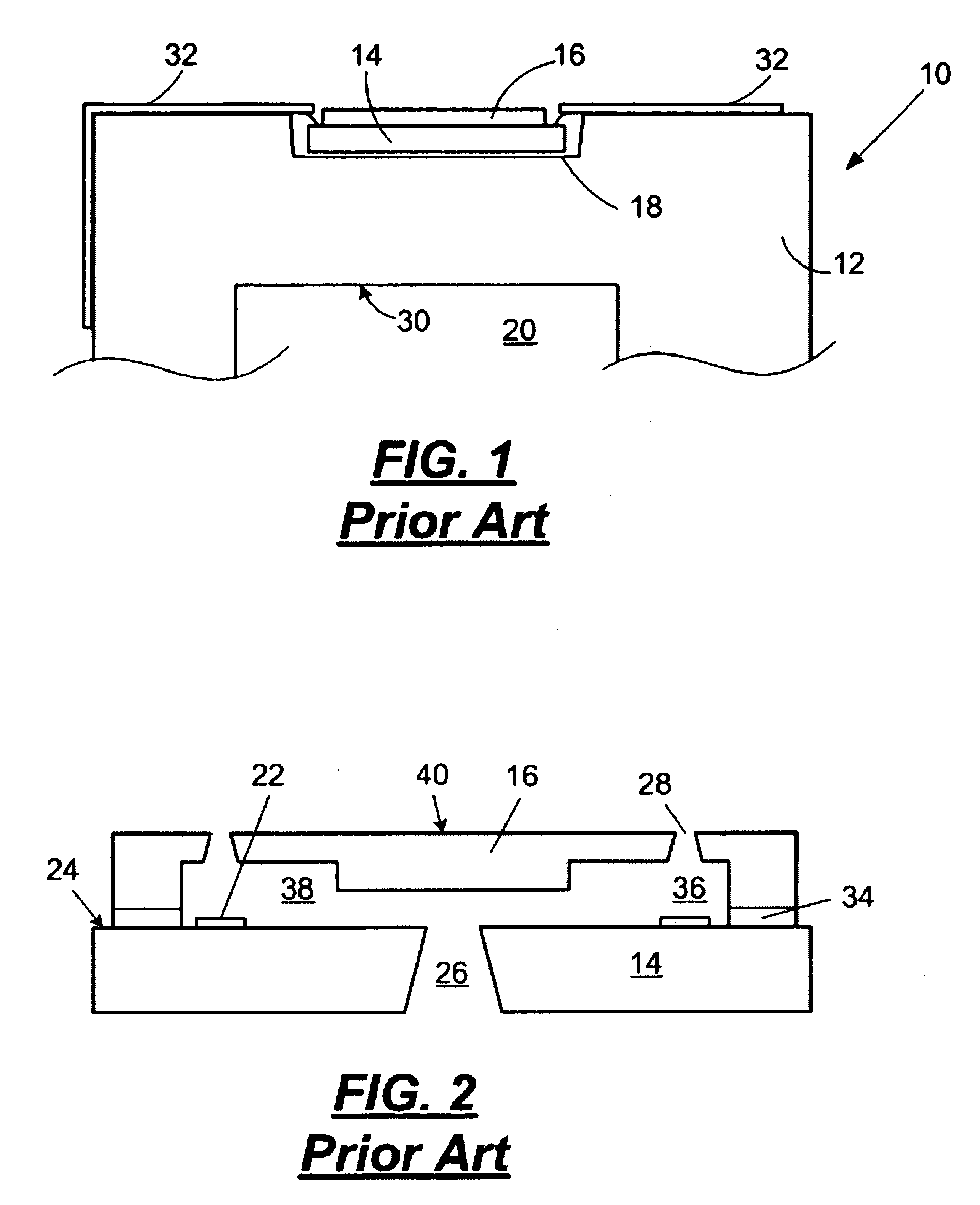
[0019] With reference to FIG. 1, there is shown a simplified representation of a portion of a prior art micro-fluid ejection head 10, for example an ink jet printhead, viewed from one side and attached to a fluid cartridge body 12. The ejection head 10 includes a substrate 14 and a nozzle member 16. For conventional ink jet printheads, the nozzle member 16 is formed in a film, excised from the film and attached as a separate component to the substrate 14 using an adhesive. The substrate / nozzle member assembly 14 / 16 is attached in a chip pocket 18 in the cartridge body 12 to form the ejection head 10. Fluid to be ejected, such as an ink, is supplied to the substrate / nozzle member assembly 14 / 16 from a fluid reservoir 20 in the cartridge body 12 generally opposite the chip pocket 18.

[0020] The cartridge body 12 may preferably be made of a metal or a polymeric material selected from the group consisting of amorphous thermoplastic polyetherimide available from G.E. Plastics of Huntersv...


PUM


Abstract

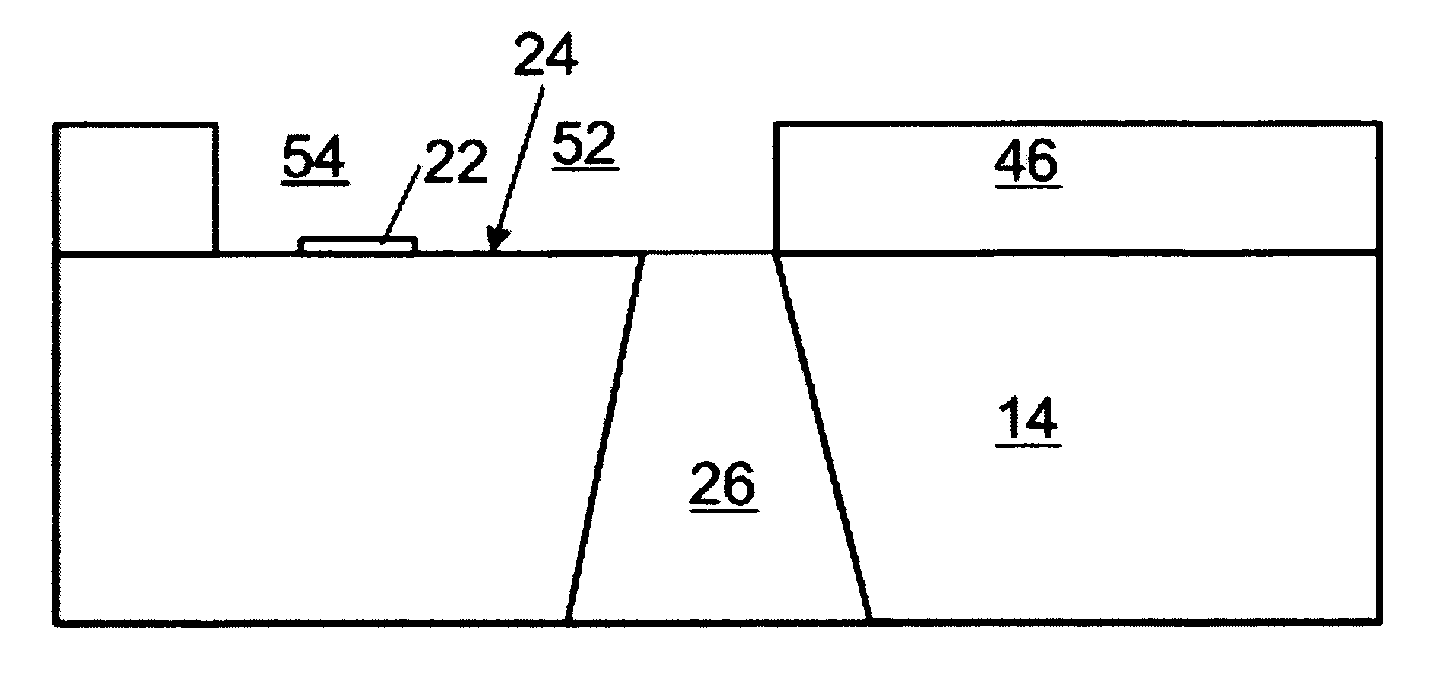
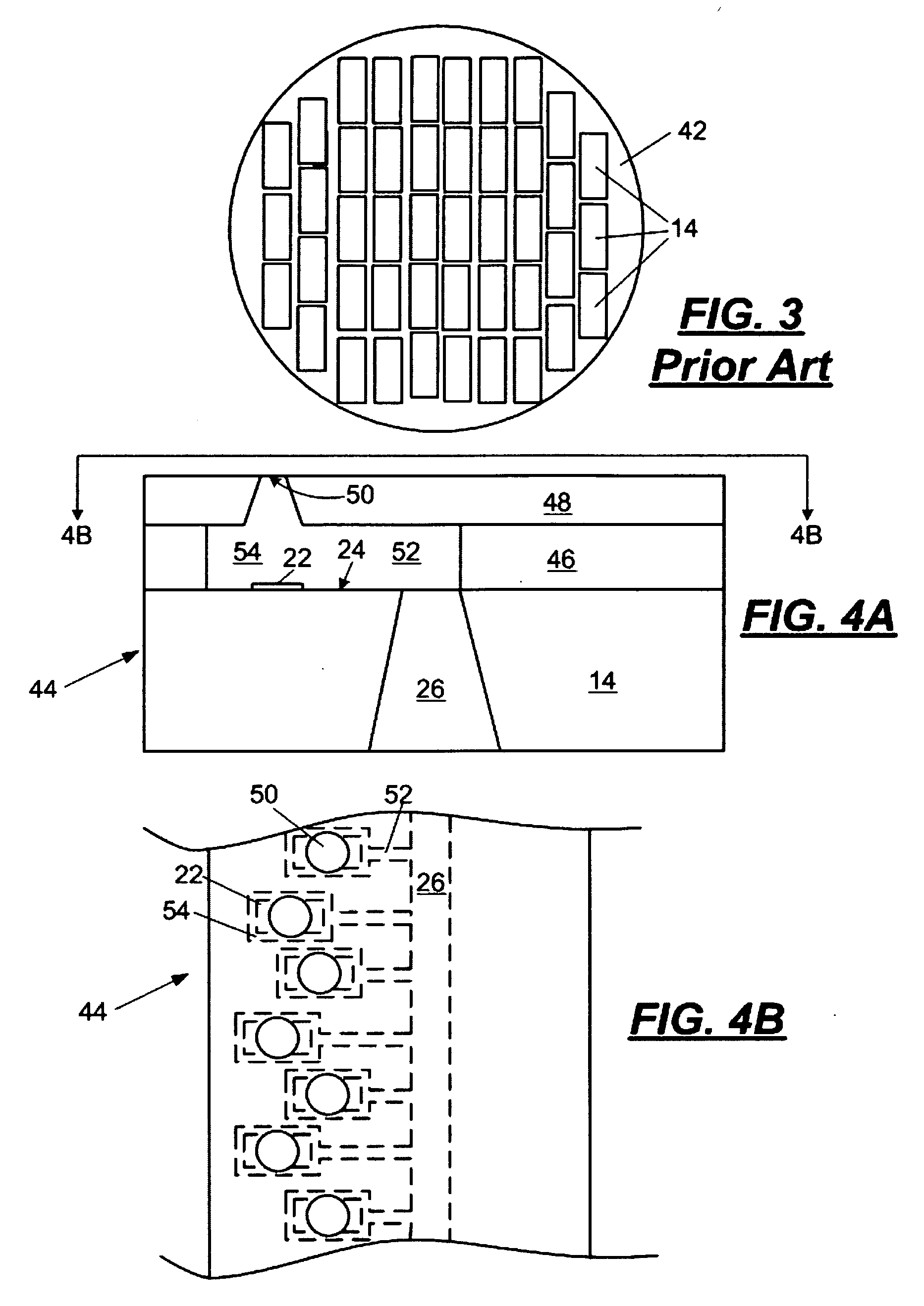
Methods of making micro-fluid ejection head structures. One of the methods includes providing a substrate having a plurality fluid ejection actuators on a device surface thereof. The device surface of the substrate also has a thick film layer comprising at least one of fluid flow channels and fluid ejection chambers therein. A removable anti-reflective material is applied to at least one or more exposed portions of the device surface of the substrate. A nozzle layer is applied adjacent to the thick film layer. The nozzle layer is imaged to provide a plurality of nozzles in the nozzle layer, and the non-reflective material is removed from the exposed portions of the device surface of the substrate.

Description

FIELD [0001] The disclosure relates to micro-fluid ejection devices, and in particular to improved methods for making micro-fluid ejection head structures that have precisely formed flow features. BACKGROUND AND SUMMARY [0002] Micro-fluid ejection heads are useful for ejecting a variety of fluids including inks, cooling fluids, pharmaceuticals, lubricants and the like. A widely used micro-fluid ejection head is in an ink jet printer. Ink jet printers continue to be improved as the technology for making the micro-fluid ejection heads continues to advance. New techniques are constantly being developed to provide low cost, highly reliable printers which approach the speed and quality of laser printers. An added benefit of ink jet printers is that color images can be produced at a fraction of the cost of laser printers with as good or better quality than laser printers. All of the foregoing benefits exhibited by ink jet printers have also increased the competitiveness of suppliers to pr...

Claims


Application Information

Patent Timeline
IPC IPC(8): B41J2/135
CPCB41J2/1433B41J2/1603B41J2/162B41J2/1623B41J2/1628B41J2/1645B41J2/1632B41J2/1634B41J2/1635B41J2/1639B41J2/1631Y10S430/146
Inventor BERTELSEN, CRAIG M.HART, BRIAN C.WALDECK, MELISSA M.WEAVER, SEAN T.
Owner FUNAI ELECTRIC CO LTD
Learn More