6K pulse repetition rate and above gas discharge laser system solid state pulse power system improvements

a laser system and pulse power technology, applied in the field of gas discharge laser systems, can solve problems such as too much dithering

Inactive Publication Date: 2007-03-29
CYMER INC
View PDF99 Cites 35 Cited by
  • Summary
  • Abstract
  • Description
  • Claims
  • Application Information

AI Technical Summary

Benefits of technology

[0029] A method and apparatus for operating a very high repetition gas discharge laser system magnetic switch pulsed power system is disclosed, which may comprise a solid state switch, a charging power supply electrically connected to one side of the solid state switch; a charging inductor electrically connected to the other side of the solid state switch; a deque circuit electrically in parallel with the solid state switch comprising a deque switch; a peaking capacitor electrically connected to the charging inductor, a peaking capacitor charging control system operative to charge the peaking capacitor by opening the deque switch and leaving the solid state switch open and then shutting the solid state switch. The solid state switch may comprise a plurality of solid state switches electrically in parallel. The peaking capacitor charging control system may be operative to charge the peaking capacitor by leaving the deque switch open until substantially all of the electrical energy stored in the charging inductor has been removed before shutting the solid state switch. The very high repetition gas discharge laser system magnetic switch pulsed power system may comprise a solid state switch; a charging power supply electrically connected to one side of the solid state switch; a charging inductor electrically connected to the other side of the solid state switch; a peaking capacitor electrically connected to the charging inductor, a delay circuit operative to charge the peaking capacitor with electrical energy stored in the charging inductor prior to shutting the solid state switch. The very high repetition gas discharge laser system magnetic switch pulsed power system may comprise a step-up transformer comprising a plurality of winding pucks each comprising a turn primary winding around a secondary winding; each of the plurality of pucks contained in at least two separate sections of primary winding pucks laid out on a step-up transfer mounting board at angles to each other generally forming an L or a U or an O shaped compilation having a first and a second end; a cooling plate having a plurality of sections ea

Problems solved by technology

Due to the extreme charge rate of this system, too much dither

Method used


Image

  • 6K pulse repetition rate and above gas discharge laser system solid state pulse power system improvements
  • 6K pulse repetition rate and above gas discharge laser system solid state pulse power system improvements
  • 6K pulse repetition rate and above gas discharge laser system solid state pulse power system improvements

Examples


Embodiment Construction

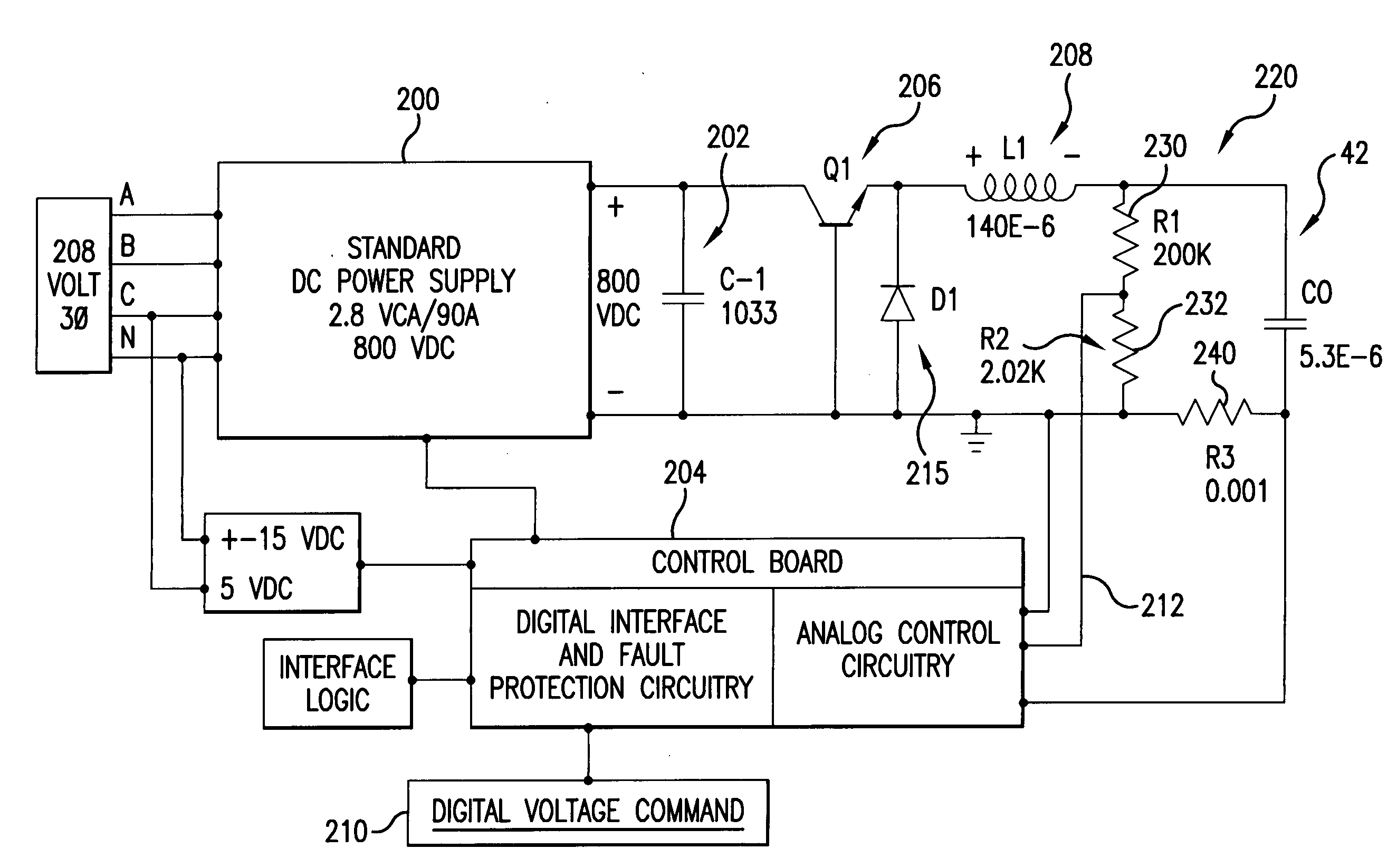
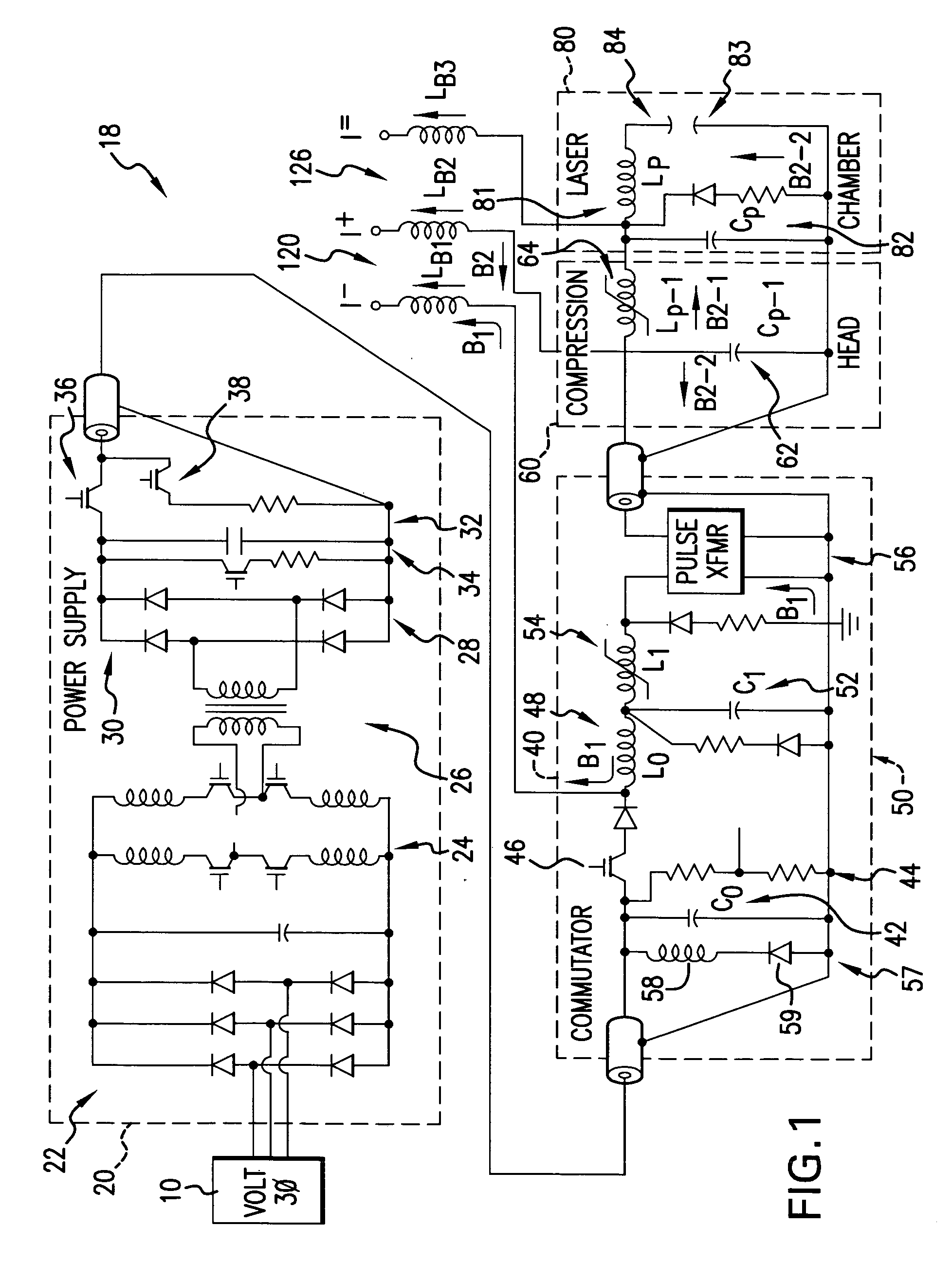
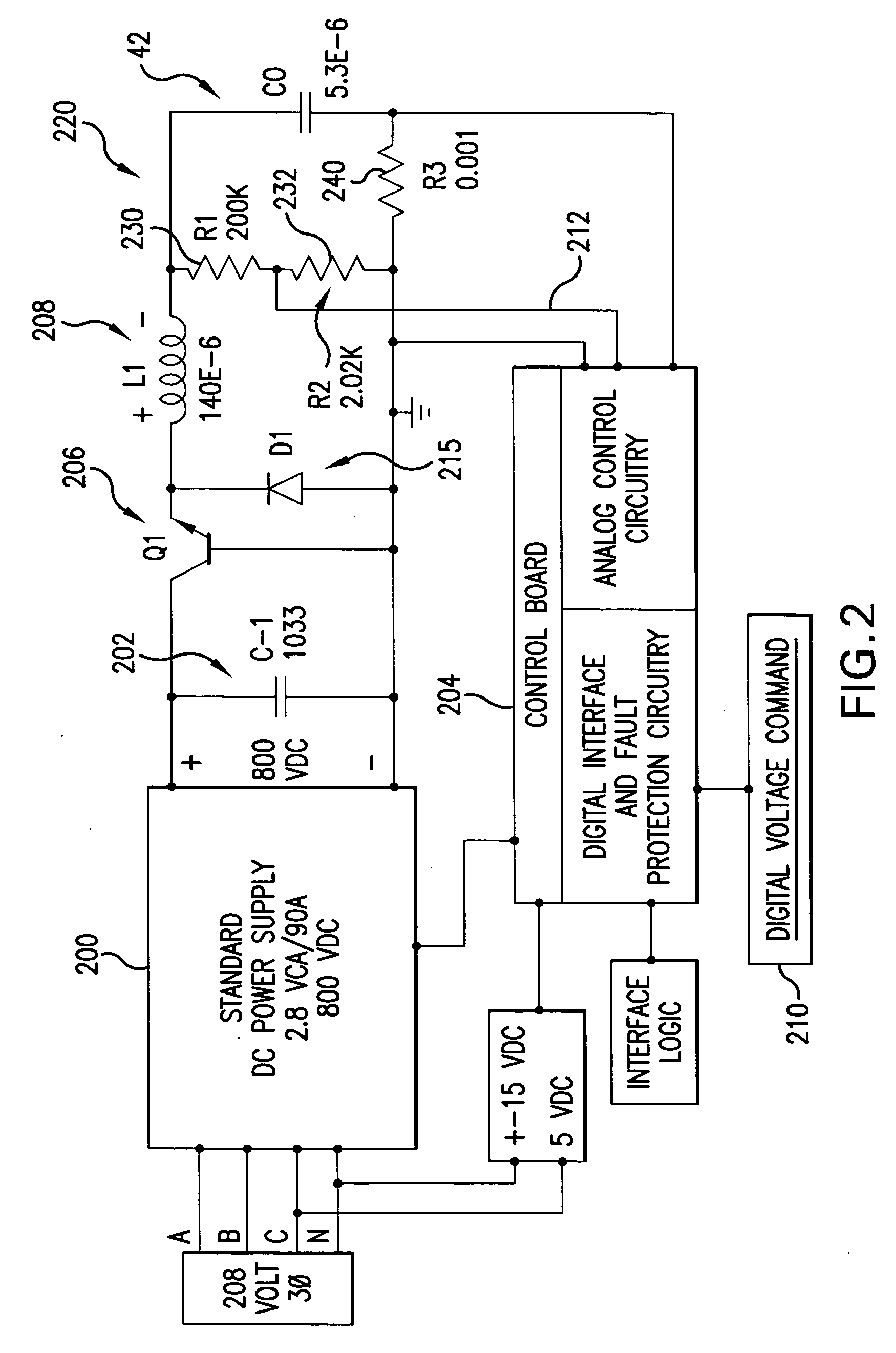
[0049] According to aspects of an embodiment of the present invention an issue to address is that the peak current in the charging inductor of a resonant charger (“RC”) module, e.g., 220 shown illustratively in FIGS. 2 and 3 can increase with the 2nd (and on) pulses in a burst of laser system pulsed output light beam pulses since current (stored or recovered energy) may already exist in the charging inductor, e.g., inductor L1208 shown, e.g., in FIGS. 2 and 3, remaining from the energy recovery cycle of the previous pulse. When the charging switch, e.g., switch Q1206 shown illustratively in FIGS. 2 and 3, is closed, current also flows from the C-1 capacitor 202, also illustratively shown in FIGS. 2 and 3. This current adds to the already existing energy recovery current and can cause the peak current in the switch Q1206 to go higher than it would be for the first pulse. This increases the requirements (for current) of the charging switch Q1206 (and additional components e.g., D1215 ...


PUM


Abstract

A method and apparatus for operating a very high repetition gas discharge laser system magnetic switch pulsed power system is disclosed, which may comprise a solid state switch, a charging power supply electrically connected to one side of the solid state switch; a charging inductor electrically connected to the other side of the solid state switch; a deque circuit electrically in parallel with the solid state switch comprising a deque switch; a peaking capacitor electrically connected to the charging inductor, a peaking capacitor charging control system operative to charge the peaking capacitor by opening the deque switch and leaving the solid state switch open and then shutting the solid state switch. The solid state switch may comprise a plurality of solid state switches electrically in parallel.

Description

CROSS-REFERENCE TO RELATED APPLICATIONS [0001] The present application is a continuation-in-part of U.S. patent application Ser. No. 11 / 241,850, entitled GAS DISCHARGE LASER SYSTEM ELECTRODES AND POWER SUPPLY FOR DELIVERING ELECTRICAL ENERGY TO SAME, filed on Sep. 29, 2005, Attorney Docket No. 2005-0051-01, and claims priority to U.S. Patent Application No. 60 / 733,052, filed on Nov. 2, 2005, the disclosures of which is hereby incorporated by reference. The present application is related to U.S. Pat. No. 6,690,706, entitled HIGH REP-RATE LASER WITH IMPROVED ELECTRODES, issued to Morton et al. on Feb. 10, 2004, and U.S. Pat. No. 6,882,674, entitled 4 KHZ GAS DISCHARGE LASER SYSTEM, issued to Wittak et al on Apr. 19, 2005; and U.S. Pat. No. 6,442,181, entitled EXTREME REPETITION RATE GAS DISCHARGE LASER, issued to Oliver, et al. on Aug. 27, 2002; and U.S. Pat. No. 5,448,580, entitled AIR AND WATER COOLED MODULATOR, issued to Birx, et al. on Sep. 5, 1995, and U.S. Pat. No. 5,315,611, en...

Claims


Application Information

Patent Timeline
IPC IPC(8): H01S3/04H01S3/00H01S3/22H01S3/223
CPCH01S3/04H01S3/097H01S3/09702H01S3/0975H03K17/785H03K3/57H03K17/127H03K17/567H03K17/6872H01S3/225
Inventor HUANG, CHAOFENGMELCHER, PAUL C.NESS, RICHARD M.
Owner CYMER INC
Why Eureka
Try Eureka