Developing device and image-forming apparatus

a development device and image-forming technology, applied in the field of developing devices and image-forming apparatuses, can solve the problems of short service life of the developing device, reduced charge quantity, and toner charge-receiving property degradation, so as to prevent excessive consumption of reverse polarity particles, reduce influences, and prevent degradation of the carrier for a long time

Inactive Publication Date: 2007-03-29
KONICA MINOLTA BUSINESS TECH INC
View PDF11 Cites 6 Cited by
  • Summary
  • Abstract
  • Description
  • Claims
  • Application Information

AI Technical Summary

Benefits of technology

[0028] In the present invention, since the consumption of reverse polarity particles can be suppressed, it becomes possible to reduce influences caused by variations in the amount of consumption of reverse polarity particles depending on the image area rate, and consequently to prevent the reverse polarity particles from being excessively consumed, in particular when the image area rate is low (in which the toner consumption is small). Moreover, the reverse polarity particles can effectively compensate the carrier for its charging property, thereby making it possible to prevent degradation in the carrier for a long time as a result. For this reason, even in the case when an image having a comparatively small image area is continuously formed, the quantity of charge in toner can be maintained effectively for a long time.

Problems solved by technology

In contrast, due to a strong stress in the regulating section, the toner is easily deteriorated to cause degradation in the toner charge-receiving property.
Moreover, the toner regulating member and the surface of the toner-supporting member are contaminated by the toner and externally additive agents, with the result that the charge-applying property to the toner is lowered to cause problems such as fogging and the subsequent short service life of the developing device.
However, even in the case of the two-component developer, the contamination on the carrier surface due to the toner and externally additive agents also occurs to cause reduction in the quantity of charge in toner after a long-term use, resulting in problems such as fogging and toner scattering; therefore, the device service life is not sufficient, and there is a strong demand for a longer service life.
However, since a mechanism for collecting the discharged carrier is required, and since the carrier is used as a consumable supply, problems arise in costs, environmental preservation, and the like.
Moreover, since a predetermined number of printing processes need to be repeated until the ratio of the new and old carriers has been stabilized, there is a failure to maintain and effectively use the initial properties.
However, in the disclosed developing method, the amounts of consumption in the toner and the reverse polarity-chargeable particles are different depending on the image area rate, and in particular, in the case of a small image area rate, the consumption of the reverse polarity-chargeable particles becomes excessive, causing degradation in the carrier deterioration preventive effect in the developing device.

Method used


Image

  • Developing device and image-forming apparatus
  • Developing device and image-forming apparatus
  • Developing device and image-forming apparatus

Examples


examples 5-10

[0109] Toners D to I were prepared in a manner similar to toner B except that external addition treaments described in Table 2 below were carried out.

TABLE 2First externally adding processSecond externally adding processFirst particlesSecond particlesThird particles*1Reverse polarity particles*1Toner BHydrophobic*3  Hydrophobic*3  Hydrophobic*3  40 m / s forStrontium*3 40 m / s forsilica (16)*20.2silica (20)0.5titanium oxide (30)0.53 minutestitanate (350)23 minutesToner DHydrophobic0.2Hydrophobic0.5——40 m / s forStrontium240 m / s forsilica (16)silica (20)3 minutestitanate (350)3 minutesToner EHydrophobic0.2Hydrophobic0.5——40 m / s forBarium220 m / s forsilica (16)silica (20)3 minutestitanate (350)3 minutesToner FHydrophobic0.2Hydrophobic0.5Hydrophobic0.540 m / s forStrontium240 m / s forsilica (16)silica (20)titanium oxide (30)3 minutestitanate (350)3 minutesToner GHydrophobic0.2Hydrophobic0.5——40 m / s forStrontium240 m / s forsilica (16)silica (40)3 minutestitanate (350)3 minutesToner HHydrophobic...

example 11

(1) Developing Device and Setting Conditions

[0125] With respect to the developing device, developing device A and developing device B shown below were used.

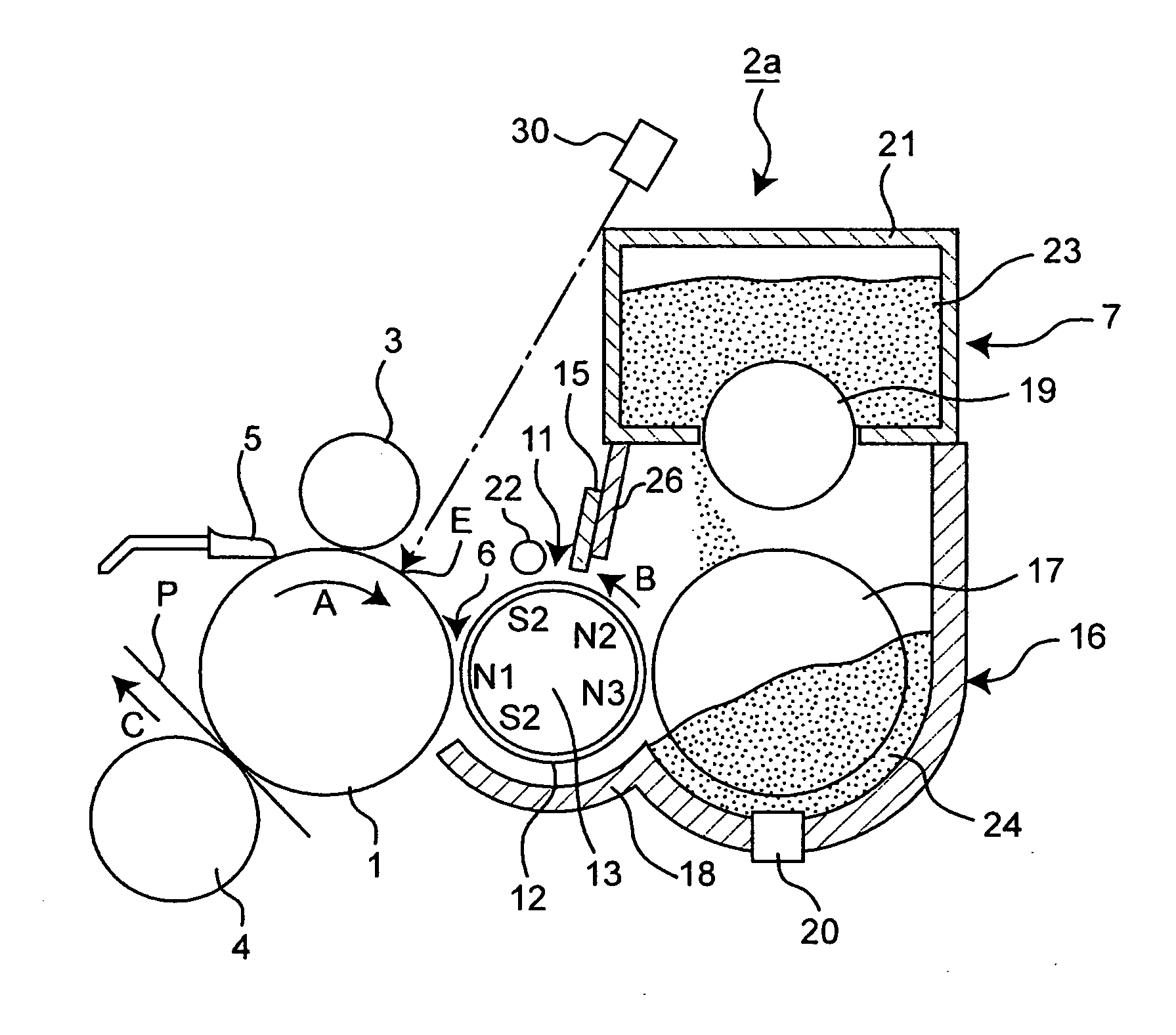
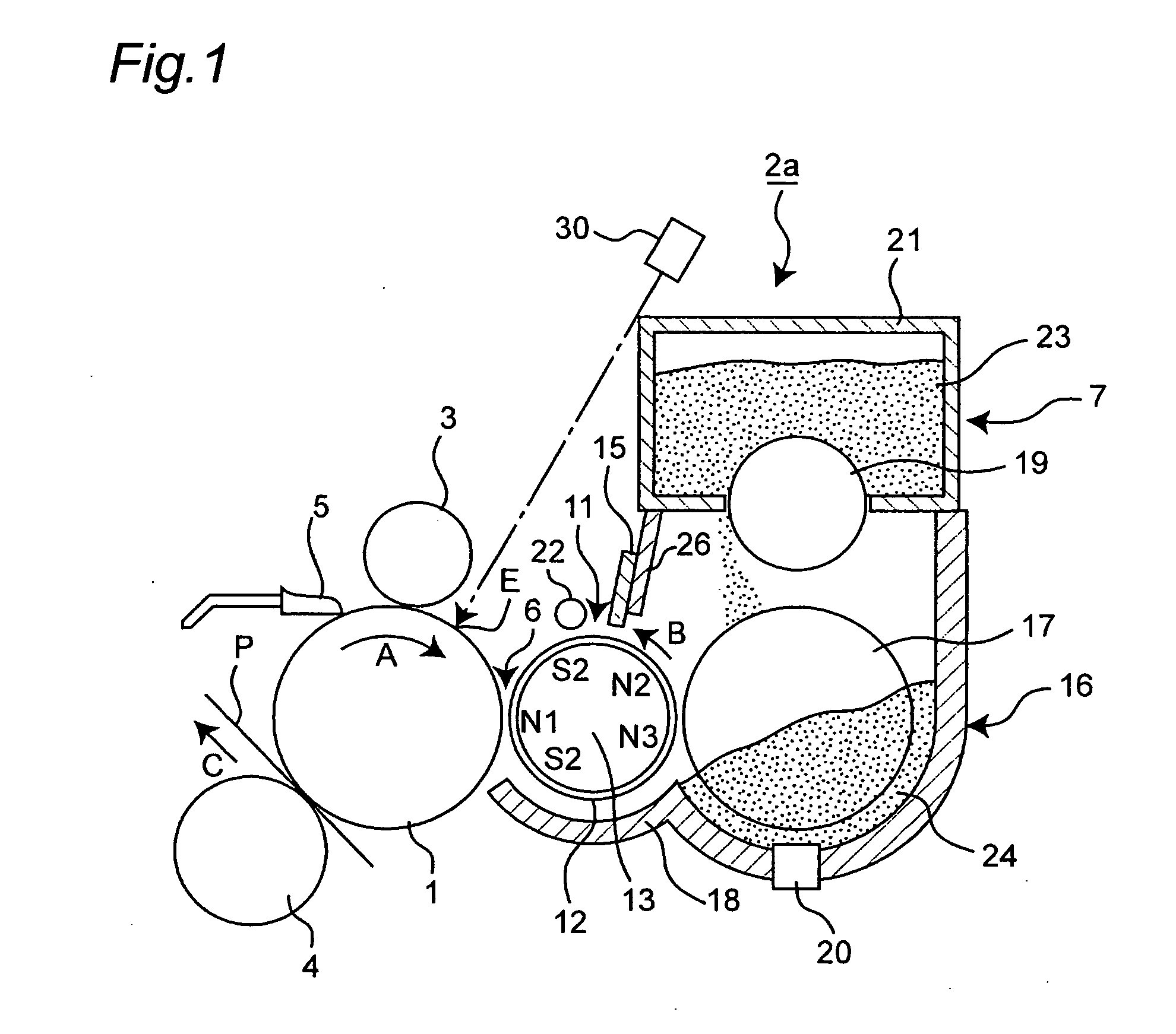
[0126] Developing device A: A developing device having a structure shown in FIG. 1 was used, and to a developer-supporting member was applied a developing bias with a rectangular wave having an amplitude of 1.4 kV, a DC component of −400 V, a Duty ratio of 50% and a frequency of 2 kHz. A DC bias of −550 V, which had a potential difference of −150 V from the average potential of the developing bias and a potential difference of 850 V from the maximum potential of the developing bias, was applied to a reverse polarity particle-collecting member. With respect to the reverse polarity particle-collecting member, an aluminum roller the surface of which was alumite-treated was used, and a gap at the closest point between the developer-supporting member and the reverse polarity particle-collecting member was set to 0.3 mm. The backgro...


PUM


Abstract

A developing device 2a, which is provided with: a developer tank 16 that houses a developer 24 containing a toner, a carrier for charging the toner and reverse polarity particles that are charged with a polarity reversed to the electrostatic charge polarity of the toner by the carrier; a developer-supporting member 11 that supports the developer supplied from the developer tank on the surface thereof, and transports the developer; and a separating mechanism 22 that separates the toner or the reverse polarity particles from the developer supported on the developer-supporting member, and the reverse polarity particles are collected into the developer tank, is provided, and an image-forming apparatus having such a developing device and an image-forming method applied thereto are also provided.

Description

[0001] This application is based on application(s) No. 2005-269676, 2005-320807 and 2006-184714 filed in Japan, the contents of which are hereby incorporated by reference. BACKGROUND OF THE INVENTION [0002] 1. Field of the Invention [0003] This invention relates to an image-forming apparatus such as a copying machine and a printer in which an electrophotographic system is used and a developing device for developing an electrostatic latent image formed on an image supporting member, and more particularly, concerns a developing device in which a developer composed of two components of a toner and a carrier and an image-forming apparatus using such a device. [0004] 2. Description of the Related Art [0005] Conventionally, with respect to a developing system for an electrostatic latent image formed on an image supporting member in the image-forming apparatus using the electrophotographic system, a one-component developing system that uses only the toner as a developer and a two-component...

Claims


Application Information

Patent Timeline
Patent Type & Authority Applications(United States)
IPC IPC(8): G03G15/09
CPCG03G15/0808G03G2215/0607G03G15/0907
Inventor UETAKE, SHIGEONAGATOMO, YUJIHIRAYAMA, JUNYAMAEYAMA, TAKESHIMATSUURA, MASAHIKONATSUHARA, TOSHIYA
Owner KONICA MINOLTA BUSINESS TECH INC
Why Eureka
Try Eureka