Heat exchanger tube and heat exchanger

a technology of heat exchanger and heat exchanger tube, which is applied in the direction of indirect heat exchanger, manufacturing tools, lighting and heating apparatus, etc., can solve the problems of increasing the probability of leakage of refrigerant due to impact of flying objects, and achieve the effect of improving the endurance to chipping

Inactive Publication Date: 2007-03-29
DENSO CORP
View PDF8 Cites 12 Cited by
  • Summary
  • Abstract
  • Description
  • Claims
  • Application Information

AI Technical Summary

Benefits of technology

[0007] As a result, there is the problem that leakage of refrigerant due to impact form flying objects is becoming more likely to occur. The present invention was made in consideration of this conventional problem and has as its object the provision of a heat exchanger tube and heat exchanger able to secure the required performance and simultaneously improve the endurance to chipping by a change in specifications of the tube.

Problems solved by technology

As a result, there is the problem that leakage of refrigerant due to impact form flying objects is becoming more likely to occur.

Method used


Image

  • Heat exchanger tube and heat exchanger
  • Heat exchanger tube and heat exchanger
  • Heat exchanger tube and heat exchanger

Examples


first embodiment and second embodiment

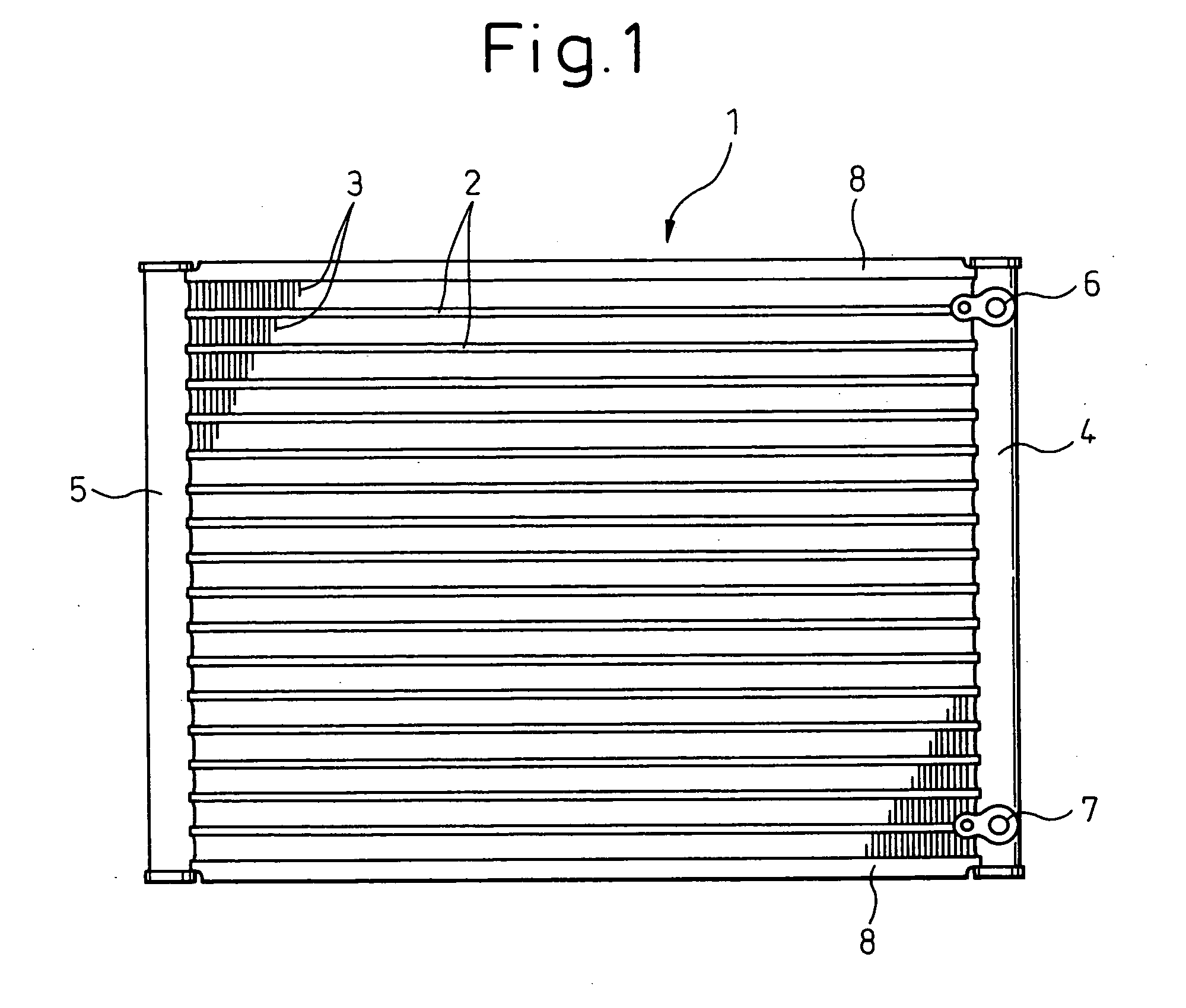
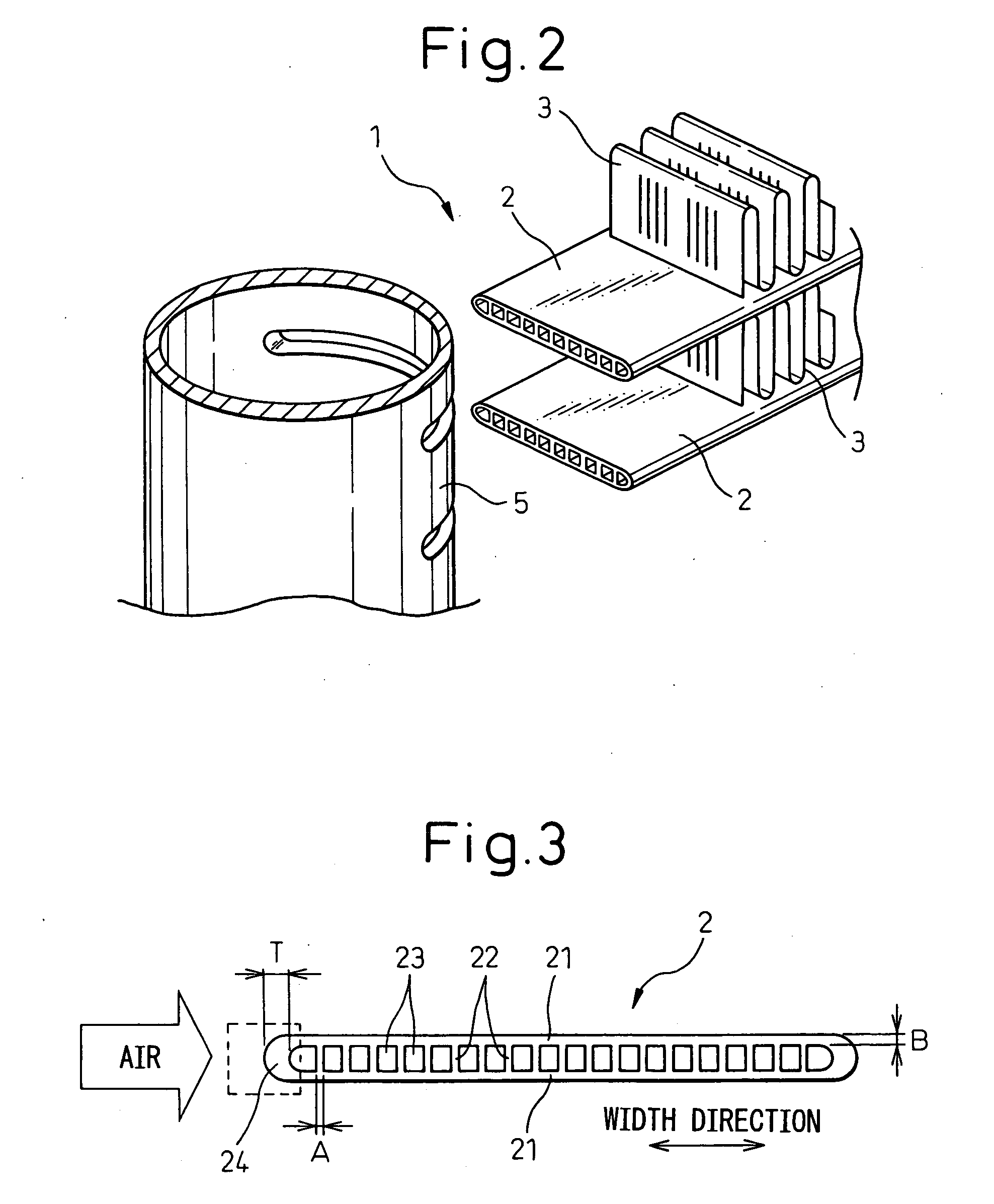
[0057] Below, a first embodiment of the present invention (corresponding to the first aspect to 12th aspect and the 16th aspect) will be explained in detail with reference to FIGS. 1 to 16. FIG. 1 is a front view of a heat exchanger 1 according to an embodiment of the present invention, while FIG. 2 is a perspective view showing heat exchanger tubes 2 and a header 5 in the heat exchanger 1 of FIG. 1 disconnected. The heat exchanger 1, as shown in FIG. 1 and FIG. 2, is a heat exchanger called a “multiflow type”.

[0058] The heat exchanger 1 is a refrigerant radiator used in a refrigeration cycle of a vehicle air-conditioning system. The refrigerant radiator can also be called a “condenser” or “radiator”. The heat exchanger 1 receives cooling air from outside the vehicle, more preferably receives wind during driving, so is exposed to the outside of the vehicle or is covered with a grille when mounted to the vehicle. For this reason, the heat exchanger 1 is easily struck by foreign matt...

second embodiment

[0116]FIG. 18 is an end view of a heat exchanger tube 2 in a second embodiment of the present invention (corresponding to aspects 13, 14). The characterizing parts different from the above embodiment will be explained. In this embodiment, the thickness “A” of the partition wall parts 22 is changed to become successively smaller from the two ends in the width direction toward the inside. In the example of FIG. 18, the thickness of the partition wall part 22a at the left end in the width direction is thicker by exactly a predetermined amount from the thickness A of the general partition wall parts 22 at the inside.

[0117] Alternatively, the width direction hole width or hole diameter of the fluid circulating holes 23 is changed to become successively smaller from the two ends in the width direction toward the inside. In the example of FIG. 18, the fluid circulating hole 23a at the right end of the width direction is the widest and the one further inside fluid circulating hole 23b is w...

third embodiment

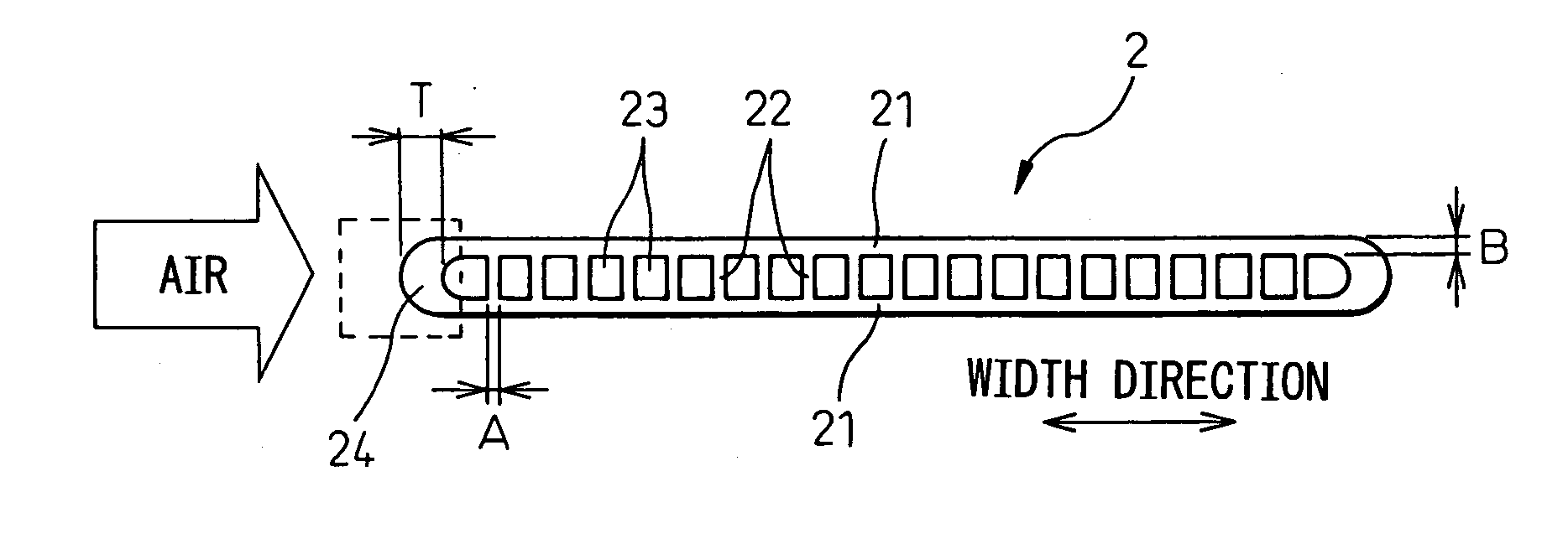
[0119]FIG. 19 is a partial end view of a heat exchanger tube 2 in a third embodiment of the present invention (corresponding to the 15th aspect). The characterizing parts different from the above embodiment will be explained. In this embodiment, a projection 24a is formed at the bottom part of the front side wall part 24. According to this, it is possible to change the tube end shape and dimensional relationship while securing performance so as to improve the endurance to chipping from the front downward direction. Note that the projection 24a may be formed at the substantial center of the heat exchanger tube 2 in the thickness direction.

Other Embodiments

[0120]FIG. 20A, FIG. 20B and FIG. 20C are end views of modifications of the heat exchanger tube 2 of the present invention. FIG. 20A shows a triangular hole type, FIG. 20B shows a joined plate type, and FIG. 20C shows an intermediate type between a rectangular hole and a circular hole type where the corners and the partition wall ...


PUM

PropertyMeasurementUnit
thicknessaaaaaaaaaa
thicknessaaaaaaaaaa
thicknessaaaaaaaaaa

Abstract

A heat exchanger tube improved in endurance to chipping, while securing performance, by changing the tube specifications, wherein, for example, fluid circulating holes are formed to be substantially rectangular in cross-section, and, when a width direction thickness of a front side wall part of the tube is “T” and a thickness of partition wall parts “A”, the relationship 3.1≦T/A≦6.1 is made to stand by the shaping process. According to this, in a rectangular hole tube, it is possible to change the dimensional relationship of the tube while securing performance so as to improve the endurance to chipping from the front frontal direction to 150 km/h (the conventional endurance being 100 km/h, a ratio to the conventional value of 1.5).

Description

BACKGROUND OF THE INVENTION [0001] 1. Field of the Invention [0002] The present invention relates to an aluminum or other metal heat exchanger tube and a heat exchanger using this tube, more particularly ones suitable for use for a condenser in a car air-conditioner etc. [0003] 2. Description of the Related Art [0004] Normally, a condenser of car air-conditioning system is arranged outside of the passenger compartment at the front end of the vehicle. The chipping etc. during driving easily deforms or damages the front surfaces of the heat exchanger tubes. Further, during vehicle operation, the tubes are exposed to rainwater, mud, exhaust gas, refuse, etc. blown into the chassis from outside. These become causes of condenser corrosion. In particular, corrosion is liable to occur starting from the deformed or damaged parts. The tubes therefore become corroded. If the corrosion progresses and holes form in the tubes, there is the problem of leakage of refrigerant. [0005] As conventiona...

Claims


Application Information

Patent Timeline
Patent Type & Authority Applications(United States)
IPC IPC(8): B28B11/00
CPCF28D1/05383Y10T428/131F28F1/022F28D1/05391
Inventor MUTO, KENMATSUO, HIROKI
Owner DENSO CORP
Why Eureka
Try Eureka