Supercharge Your Innovation With Domain-Expert AI Agents!

Two-layer optical disk and recording / reproducing optical disk apparatus of the two-layer optical disk

Inactive Publication Date: 2007-03-29
NEC CORP +1
View PDF4 Cites 2 Cited by
  • Summary
  • Abstract
  • Description
  • Claims
  • Application Information

AI Technical Summary

Benefits of technology

[0020] Accordingly, it is an object of the present invention to provide an optical disk and an optical disk apparatus which reduces the above-described problems.
[0027] According to the present invention, in the two-layer recording type optical disk which has a narrow interval between recording layers, stable recording and reproduction can be realized.

Problems solved by technology

Accordingly, if a recording operation is performed to the first recording layer across the recorded pert and the unrecorded part of the zeroth layer, the power of the condensed beam to be reached to the first recording layer is changed during the recording, comes off the optimal condition, and it is difficult to record in a good condition.
In the method that the recording on the zeroth recording layer is performed after all of the first recording layer is recorded, a control data recording area for recording control which is generally provided in an inner circumferential part of the disk has to be provided to each of the two recording layers respectively, and the processing is complicated.
Moreover, recording state of the overall two-layer optical disk cannot be checked by just reproducing the control data recording area of one of the recording layers.
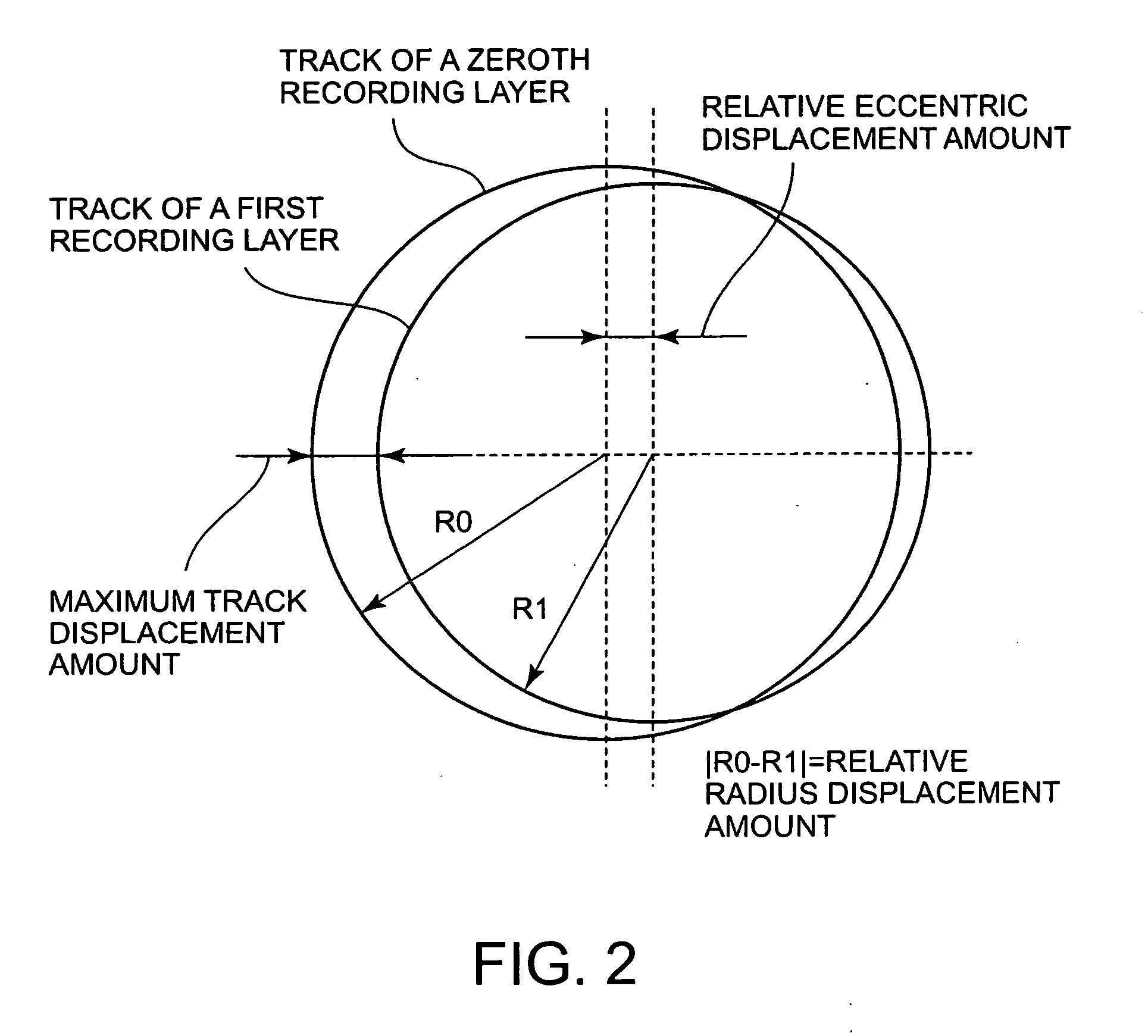
Moreover, if an interval between the two recording layers becomes narrow, other problem described below occurs.
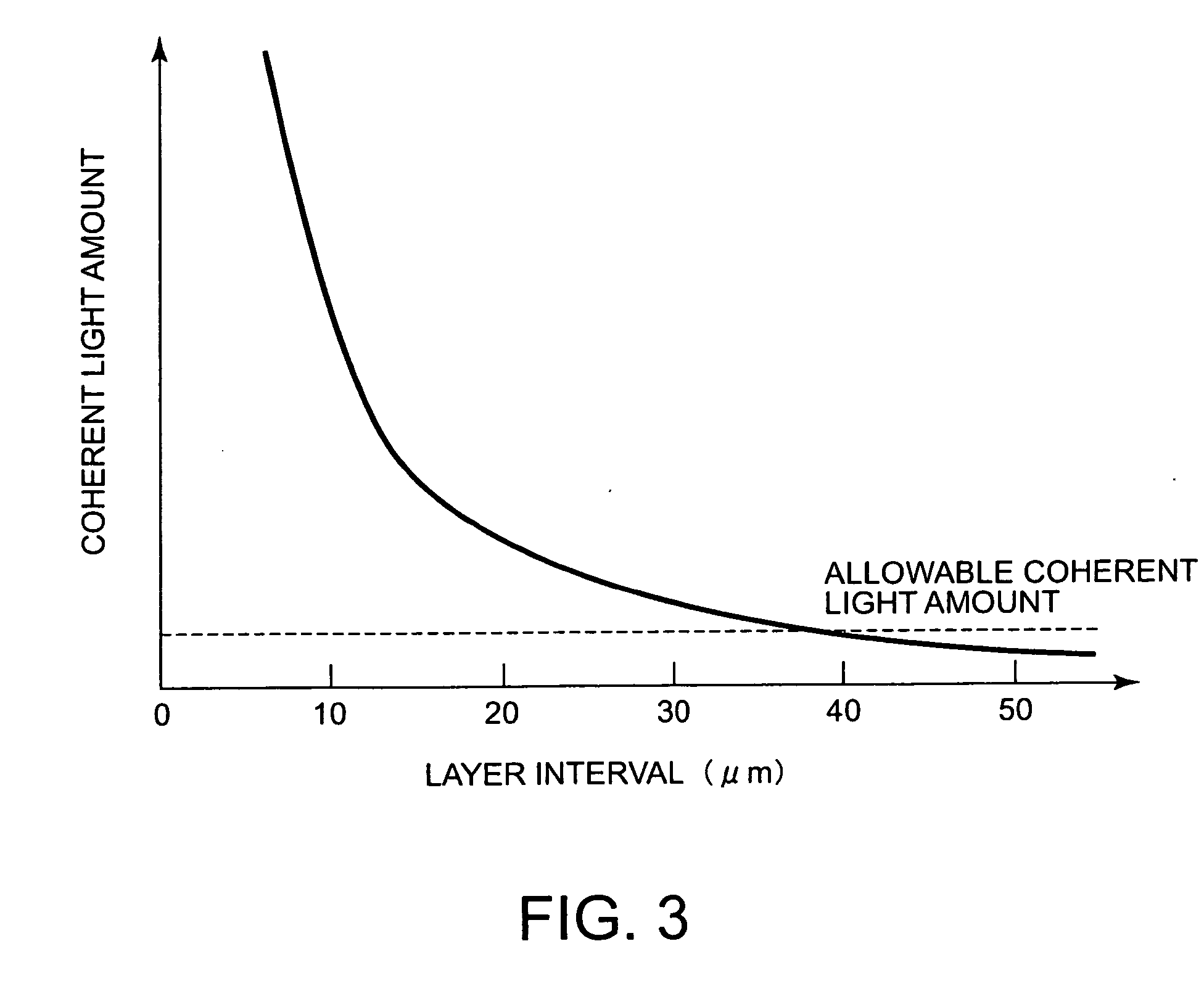
However, if the interval between the recording layers becomes narrow and an amount of the coherent light reaches the photodetector becomes to a considerable level, problems occur.
A salient problem is the two positions of the condensed beams shown in the right-hand side of the drawing in a case in which the reflected lights are generated at the border parts between the recorded part 6 and the unrecorded part 5.
In this case, imbalance of optical power is generated in the coherent light.
Accordingly, if an imbalanced coherent light is received by the optical head, the possibility to be an offset of the track error signal is high.
If such offset amount becomes significant, not only the recording operation but also the reproduction operation cannot be stably realized.
As described above, the known recording type optical disk has the problem that the recording processing on the control data recording area is complicated and in order to know a recording state, it is necessary to access to the control data recording areas of the two recording layers.
In addition, other known recording type optical disks have the problem that the optimum recording condition has to be estimated.
Moreover, the known recording optical disks has the problem that the narrower the interval between the recording layers becomes, the more affected by the coherent light.

Method used


Image

  • Two-layer optical disk and recording / reproducing optical disk apparatus of the two-layer optical disk
  • Two-layer optical disk and recording / reproducing optical disk apparatus of the two-layer optical disk
  • Two-layer optical disk and recording / reproducing optical disk apparatus of the two-layer optical disk

Examples


first embodiment

[0047] With reference to FIG. 4, an example of a format arrangement of an optical disk according to the present invention is described. In FIG. 4, the left-hand side is an inner circumference side of the optical disk and the right-hand side is an outer circumference side of the optical disk.

[0048] In each recording layer, from the inner circumference side, it is divided into an inner circumference control data recording area, a user data recording area, and an outer circumference control data recording area.

[0049] The inner circumference control data recording area of the zeroth recording layer has a blank zone 13, a guard zone 10, a test zone 11, and another recording zone 12. The other recording zone 12 has a part for appropriately recording control information about address position under recording or the like. The inner circumference control data recording area of the first recording layer has the blank zone 13, the test zone 11, and the guard zone 10.

[0050] The outer circumfe...

second embodiment

[0063] With reference to FIG. 5, a format arrangement of an optical disk according to the present invention is described. As well as shown in FIG. 4, in FIG. 5, the left-hand side is the inner circumference side and the right-hand side is the outer circumference side of the optical disk.

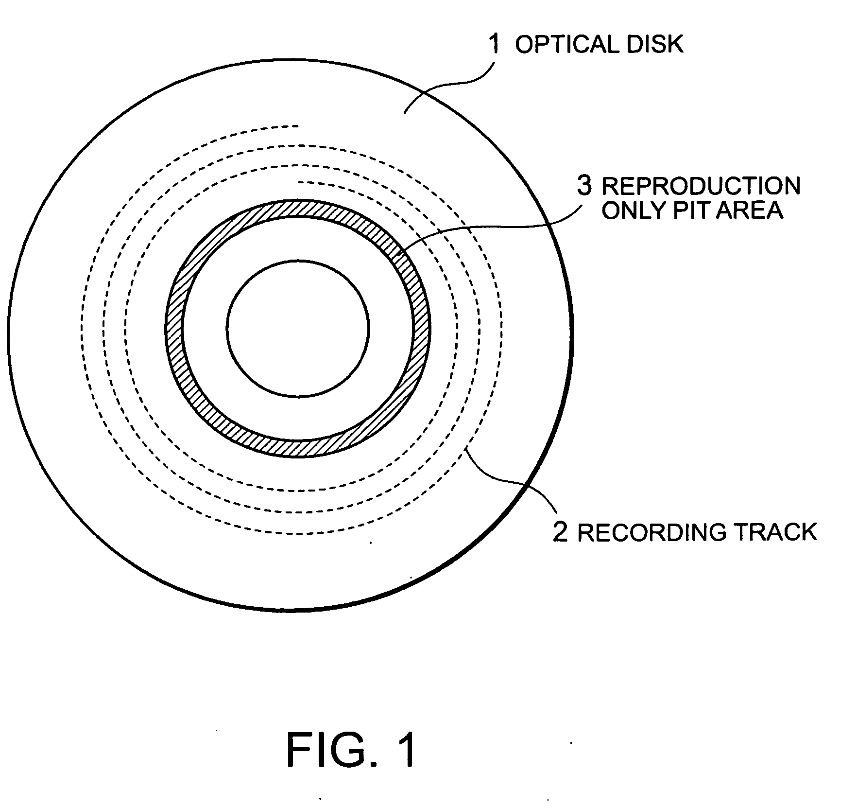
[0064] In FIG. 5, each recording layer, from the inner circumference side, has a reproduction only pit area, an unrecorded area, an inner circumference control data recording area, and a user data recording area.

[0065] Two borders of one recording layer, a border A which is between the unrecorded area and the inner circumference control data recording area and a border B which is between the inner circumference control data recording area and user data recording area, are arranged with a margin greater or equal to a predetermined clearance value against three borders of another recording layer, the border A, the border B, and a border C which is between the reproduction only pit area and the unrecor...

third embodiment

[0067]FIG. 6 is a view illustrating a structural example of a recording / reproducing optical disk apparatus according to the present invention.

[0068] The optical disk apparatus has a driving mechanism 60, a signal detection circuit 61, an address determination circuit 62, and an optical head position control circuit 63. The driving mechanism 60 has a spindle 20 for rotatively driving an optical disk 1 and an optical head 21 for writing information onto the optical disk and reading the recorded information.

[0069] The optical disk apparatus records or reproduces a signal by the optical head 21 to the two-layer optical disk I set to the spindle 20. The reproduction signal from the optical head 21 is sent to the address determination circuit 62 through the signal detection circuit 61 and a current address position of the condensed beam is detected. By this operation, it is determined whether the condensed beam is within or without the clearance value where the condensed beam is affected...


PUM


Abstract

A two-layer recording type optical disk capable of realizing stable recording and reproduction without being affected by another recording layer and an optical disk apparatus for the two-layer recording type optical disk are provided. In layouts of various areas in the optical disk, a position where a border between a recorded part and an unrecorded part is formed on one recording layer is set so that the position is always separated from a position where a border between a recorded part and an unrecorded part is formed on another recording layer by a predetermined clearance amount. Moreover, to a recording layer farther from an incident surface, test recording or data recording is always performed through a recorded part on a closer recording layer.

Description

[0001] This application claims priority to prior Japanese patent application JP 2005-263714, the disclosure of which is incorporated herein by reference. BACKGROUND OF THE INVENTION [0002] 1. Field of the Invention [0003] The present invention relates to a recording / reproducing optical disk apparatus (recording type optical disk apparatus) for recording or reproducing data by a very small optical spot and a two-layer optical disk used with the recording type optical disk apparatus. [0004] 2. Description of the Related Art [0005] In the field of optical disks which record or reproduce data by a very small optical spot, in addition to reproduction only optical disk ROM (Read Only Memory) media on which embossed data pit arrays are formed in advance, CD-Rs (Compact Disc-Recordable) and DVD-Rs (Digital Versatile Disc-Recordable), which are optical disks capable of recording data, have been widely used. Also, CD-RWs (CD-ReWritable) and DVD-RWs (DVD-ReWritable), which can rewrite recorded...

Claims


Application Information

Patent Timeline
IPC IPC(8): B32B3/02
CPCG11B7/24038G11B7/00736
Inventor YAMANAKA, YUTAKAOHKUBO, SHUICHIWATABE, KAZUOKASHIHARA, YUTAKAOGAWA, AKIHITO
Owner NEC CORP
Features
  • R&D
  • Intellectual Property
  • Life Sciences
  • Materials
  • Tech Scout
  • Unparalleled Data Quality
  • Higher Quality Content
  • 60% Fewer Hallucinations
Learn More