Radio-frequency communication device

a radio frequency communication and frequency technology, applied in the direction of modulation, amplitude modulation, transmission, etc., can solve the problems of significant change of the condition in which the transmitted signal is generated by unnecessary leakage, wave or signal disturbs the reception of the reply wave, and affects the radio communication between the interrogator and the transponder, so as to achieve a high degree of sensitivity of reception and eliminate unnecessary waves

Active Publication Date: 2007-03-29
BROTHER KOGYO KK
View PDF3 Cites 50 Cited by
  • Summary
  • Abstract
  • Description
  • Claims
  • Application Information

AI Technical Summary

Benefits of technology

[0041] According to a third preferred form of the above-described second aspect of this invention, the cancel-signal control portion further includes a transmission / reception control portion operable to control the carrier transmitting portion to transmit toward the transponder the carrier wave modulated by the carrier modulating portion, immediately after an operation of the cancel-signal control portion for controlling the carrier generating portion, and to control the signal receiving portion to receive a reply signal transmitted from the transponder in response to the modulated carrier wave received from the carrier modulating portion through the carrier transmitting portion. In this form of the invention wherein the modulated carrier wave is transmitted from the carrier modulating portion through the carrier transmitting portion, and the reply signal transmitted from the transponder is received by the signal receiving portion, immediately after the operation of the cancel-signal control portion to control the phase and amplitude of the cancel signal. Accordingly, the communication with the transponder can be effected with a high degree of sensitivity of reception of the reply signal, and a high degree of elimination of the unnecessary wave by the cancel signal the phase and amplitude of which have been optimized by the cancel-signal control portion.

Problems solved by technology

Thus, the transmitted wave or signal disturbs the reception of the reply wave or signal.
However, the conventional techniques described above have the following problems, in view of increasing introduction of the RFID system into various fields of industry.
Namely, in the field of searching for desired articles of commodity within a warehouse, for example, radio communication between the interrogator and the transponders is adversely influenced by moving persons or metallic bodies, or existence of metallic bodies.
Described in detail, the increasing introduction of the RFID system into the various fields of industry causes an increase of an influence of a change of the operating environment of the RFID system on the communication between the interrogator and the transponders, resulting in a considerable change of the condition in which the unnecessary leakage signal is generated from the transmitted signal or wave.
Thus, it has been difficult to deal with a change of the operating environment of the RFID system in a real-time fashion, for sufficiently canceling the interfering leakage signal with the suitably adjusted cancel signal, to maintain a high degree of reception sensitivity of the interrogator or radio-frequency communication device.
The conventional techniques have another problem that the influence of the transmitted signal on the reception of the received signal changes each time the direction of transmission of the transmitted signal is changed.
That is, a part of the transmitted signal transmitted from the radio-frequency communication device is mixed as a leakage signal into the received signal received by the radio-frequency communication device, so that the communication between the radio-frequency communication device and the communication object is adversely influenced by the leakage signal.
However, the change of the direction of transmission of the transmitted signal causes a change of the influence of the leakage signal on the received signal, so that it is difficult to sufficiently eliminate the influence of the leakage signal.

Method used


Image

  • Radio-frequency communication device
  • Radio-frequency communication device
  • Radio-frequency communication device

Examples


embodiment 1

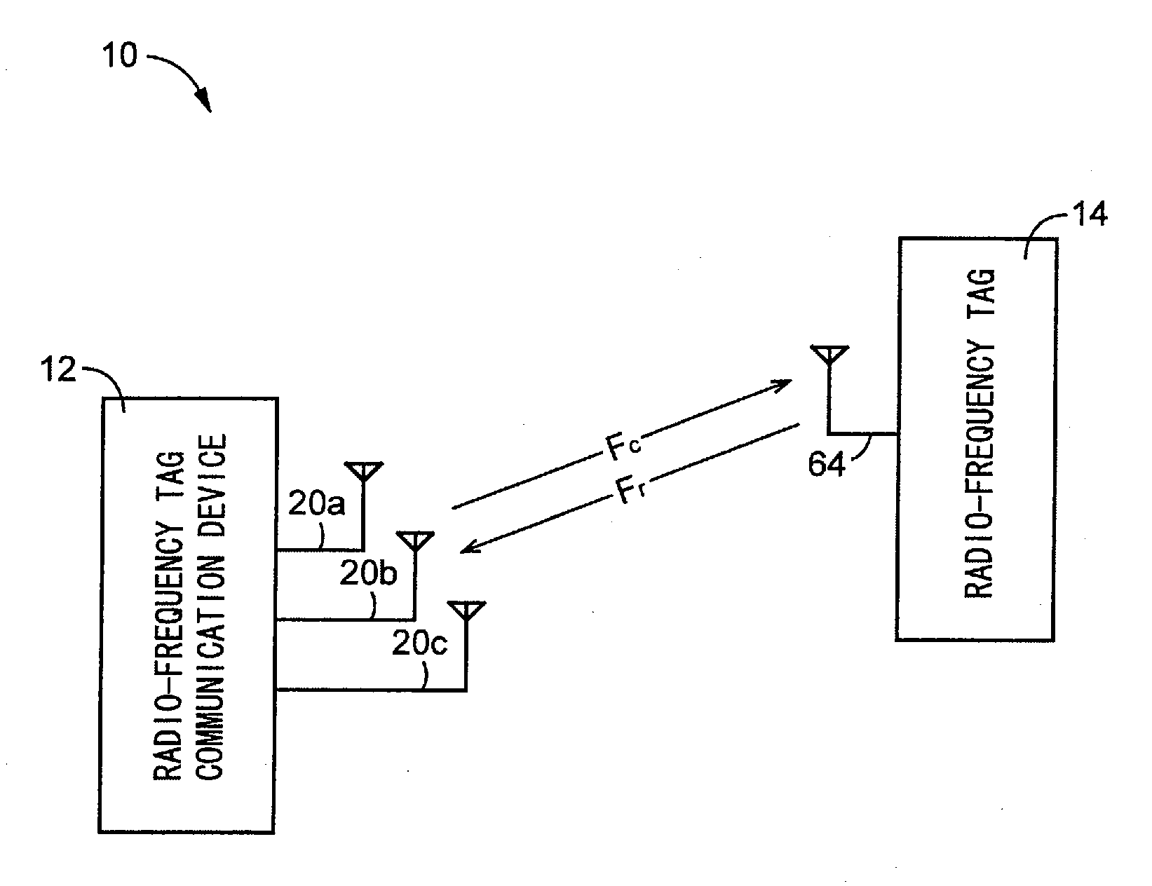
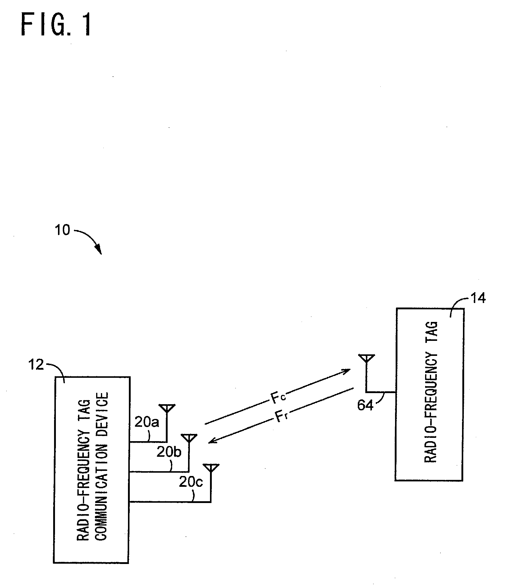
[0063] Referring to FIG. 1, there is shown an arrangement of a radio-frequency communication system 10, which is a so-called RFID (radio-frequency identification) system including a radio-frequency tag communication device 12 constructed according to a first embodiment of this invention, and at least one radio-frequency tag 14. In FIG. 1, only one radio-frequency tag 14 is shown. The radio-frequency tag communication device 12 functions as an interrogator of the RFID system, while the radio-frequency tag 14 functions as a transponder of the RFID system. When a interrogating wave (transmitted signal) Fc, is transmitted from the radio-frequency tag communication device 12 toward the radio-frequency tag 14, the interrogating wave Fc, received by the radio-frequency tag 14 is modulated into a reply wave Fr (reply signal) according to a predetermined information signal (data) stored in the radio-frequency tag 14, and the reply wave Fr is transmitted from the radio-frequency tag 14 toward...

embodiment 2

[0095] Referring to FIG. 7, there will be described an electrical arrangement of a radio-frequency tag communication device 80 constructed according to a second embodiment of the present invention. As shown in FIG. 7, the radio-frequency tag communication device 80 according to the second embodiment includes a wave detecting portion 82 functioning as a local-signal oscillator operable to generate local signals on the basis of the carrier waves received from the carrier generating portion 16, and to combine together the generated local signals and the received signals received by the plurality of transmitter / receiver antenna elements 20. This wave detecting portion 82 includes: a plurality of local-signal-phase control portions (three control portions in the embodiment as shown in FIG. 7) 84a, 84b, 84c (hereinafter referred to simply as “local-signal-phase control portions 84”, unless otherwise specified) operable to control the phases of the carrier waves received from the carrier g...

embodiment 3

[0104] Referring next to FIG. 8, there will be described an overall arrangement of a radio-frequency tag communication system S including a radio-frequency communication device in the form of an interrogator 100 constructed according to a third embodiment of this invention, and a transponder in the form of the radio-frequency tag 14 described above.

[0105] The interrogator 100 includes: an antenna 101 for radio communication between a circuit element To of the radio-frequency tag 14 and the antenna 101; a high-frequency circuit 102 operable to obtain access to (to read and write information on or from) an IC circuit portion 65 of the circuit element To; a signal-processing circuit 103 operable to process signals read out from the circuit element To; a control circuit 104 operable to control the operation of the interrogator 100.

[0106] The control circuit 104 is a so-called microcomputer incorporating a central processing unit (CPU), a ROM and a RAM, which are not shown in FIG. 8. T...


PUM


Abstract

A radio-frequency communication device arranged to transmit a transmitted signal from a transmitter antenna device toward a communication object, and to receive through a receiver antenna device a reply signal transmitted from the communication object, for radio communication with the communication object, the radio-frequency communication device including a transfer-function calculating portion operable to calculate a transfer function indicative of a relationship between a signal input to the transmitter antenna device and a signal generated by the receiver antenna device due to the signal input to the transmitter antenna device, and a receiver-circuit-constant setting portion operable to set a receiver-circuit constant for improving a quality of the reply signal received by the receiver antenna device, on the basis of the transfer function calculated by the transfer-function calculating portion, and the signal input to the transmitter antenna device.

Description

[0001] The present application is a Continuation-in-Part of International Application No. PCT / JP2005 / 007343 filed Apr. 15, 2005, which claims the benefits of Japanese Patent Applications No. 2004-145298 filed May 14, 2004 and No. 2004-190098 filed Jun. 28, 2004. BACKGROUND OF THE INVENTION [0002] 1. Field of the Invention [0003] The present invention relates in general to a radio-frequency communication device operable to transmit and receive information to and from a desired communication object, and more particularly to techniques for eliminating an influence of a transmitter side of the device on a receiver side of the device. [0004] 2. Description of the Related Art [0005] In various fields of data communication, there are used radio-frequency communication devices arranged to transmit transmitted signals toward desired communication objects, and to receive received signals transmitted from the communication objects in response to the transmitted signals, for thereby effecting c...

Claims


Application Information

Patent Timeline
Patent Type & Authority Applications(United States)
IPC IPC(8): H04B1/16H01Q3/26H04B1/40H04B1/59
CPCH01Q3/26
Inventor NAGAI, TAKUYAUSHIYAMA, KENTARO
Owner BROTHER KOGYO KK
Why Eureka
Try Eureka