Beam exposure writing strategy system and method

a technology of exposure and writing strategy, applied in the direction of electrical equipment, nanotechnology, electric discharge tubes, etc., can solve the problems of limiting the feature resolution and critical dimension (cd) uniformity of flash profiles, and reducing the basic address uni

Inactive Publication Date: 2007-04-05
APPLIED MATERIALS INC
View PDF13 Cites 13 Cited by
  • Summary
  • Abstract
  • Description
  • Claims
  • Application Information

AI Technical Summary

Problems solved by technology

The limited flash profile limits feature resolution and critical dimension (CD) uniformity.
However, improving the resolution requires reducing the basic address unit.
Such reduction results in the lengthening of the printing time quadratically.
However, the fundamental limitations (feature resolution and CD uniformity) have not been alleviated thereby.
A vector shaped beam method may have the disadvantage for some applications for some applications of slow flash rate.
A raster shaped beam system unfortunately may retain the disadvantage for some applications of the raster Gaussian beam system.
In this regard, further improvements to the feature resolution may, for certain applications, quadratically lengthen printing time, or at least lengthen it significantly.

Method used


Image

  • Beam exposure writing strategy system and method
  • Beam exposure writing strategy system and method
  • Beam exposure writing strategy system and method

Examples


Embodiment Construction

[0022] It will be readily understood that the components of the embodiments as generally described and illustrated in the drawings herein, could be arranged and designed in a wide variety of different configurations. Thus, the following more detailed description of the embodiments of the system, components and method of the present invention, as represented in the drawings, is not intended to limit the scope of the invention, as claimed, but is merely representative of the embodiment of the invention.

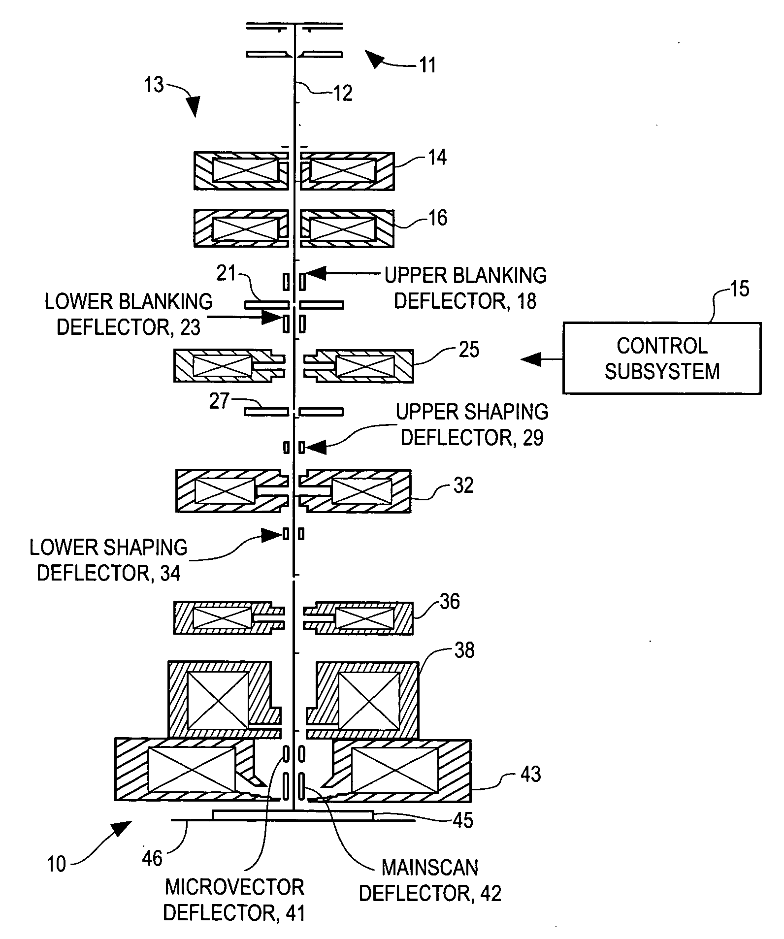
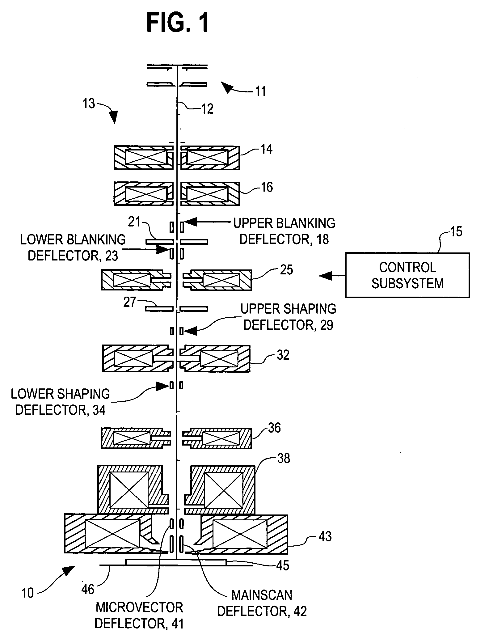
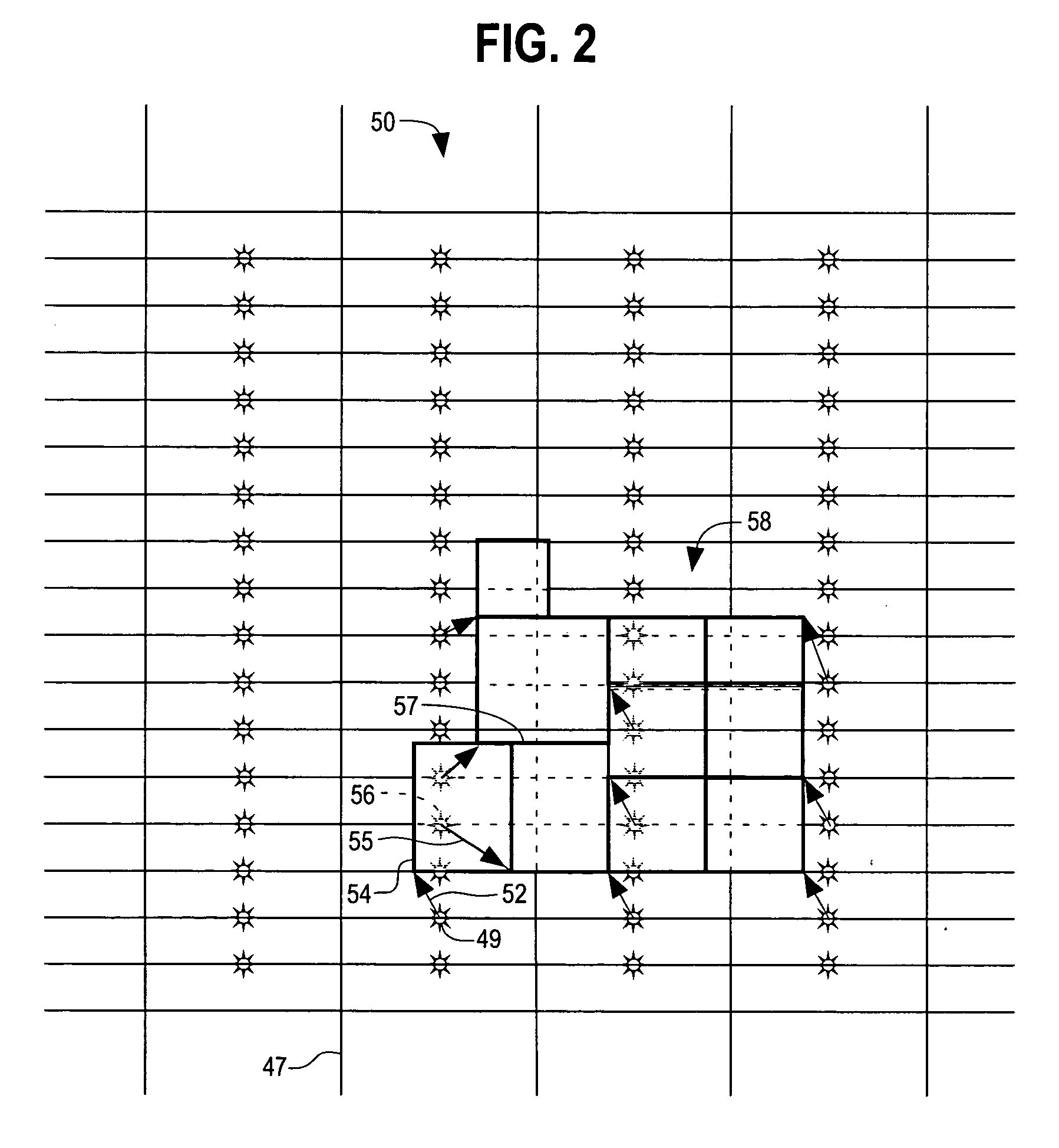
[0023] A beam exposure writing strategy method and system are disclosed for exposing a desired pattern on a substrate, by raster scanning a beam such as a particle beam, across a major field on the substrate. The beam is also vector scanned across a minor field of the substrate superimposed along the major field raster scan. The beam is selectively blanked and unblanked as the beam is being scanned. The unblanked flashes of the beam are modulated in coordination with the raster and vec...


PUM


Abstract

A beam exposure writing strategy method and system are disclosed for exposing a desired pattern on a substrate, by raster scanning a beam such as a particle beam, across a major field on the substrate. The beam is also vector scanned across a minor field of the substrate superimposed along the major field raster scan. The beam is selectively blanked and unblanked as the beam is being scanned. The unblanked flashes of the beam are modulated in coordination with the raster and vector scanning to expose the desired pattern on the substrate. The disclosed system and method generating an adjustable length microvector having a maximum range of at least about N time a nominal length λ, where N is equal to four and λ is substantially equal to a dimension of a nominal flash area, the nominal flash location dimension being substantially greater than a major field cell dimension.

Description

RELATED APPLICATIONS [0001] This application is related to U.S. Patent Application No. (docket 9790), filed Oct. 3, 2005 entitled “WRITING A CIRCUIT DESIGN PATTERN WITH SHAPED. PARTICLE BEAM FLASHES,” incorporated herein by reference as if set forth herein in its entirety. FIELD OF THE INVENTION [0002] The present invention in general relates to a beam exposure writing strategy system and method. The invention more particularly relates to a system and method for facilitating the exposing of a pattern on a substrate by means of a beam, such as a particle beam or an optical beam, for an application such as for lithographic purposes. BACKGROUND ART [0003] There is no admission that the background art disclosed in this section legally constitutes prior art. [0004] In certain types of beam writing systems, such as systems used for lithography, beams of energy are directed onto a coated substrate for interacting with it to form desired patterns. During a scan sequence of the beam, the pat...

Claims


Application Information

Patent Timeline
Patent Type & Authority Applications(United States)
IPC IPC(8): H01J37/302
CPCB82Y10/00B82Y40/00H01J37/3026H01J37/3174H01J2237/30488H01J2237/30494
Inventor BULLER, BENYAMINLOZES, RICHARD L.
Owner APPLIED MATERIALS INC
Why Eureka
Try Eureka