Eureka AIR delivers breakthrough ideas for toughest innovation challenges, trusted by R&D personnel around the world.

External resonator/cavity electrode-less plasma lamp and method of exciting with radio-frequency energy

Active Publication Date: 2007-04-05
TOPANGA USA
View PDF8 Cites 37 Cited by
  • Summary
  • Abstract
  • Description
  • Claims
  • Application Information

AI Technical Summary

Benefits of technology

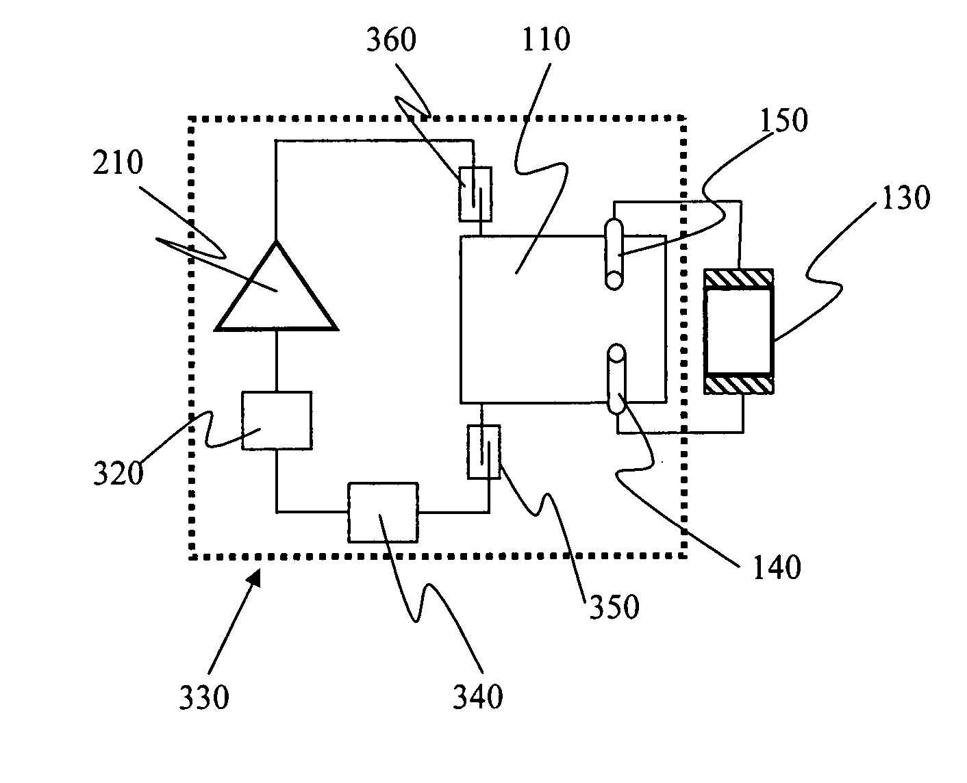
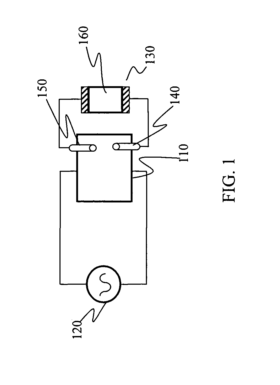
[0006] This invention provides distinct advantages over electrode-less plasma lamps in the background art. Firstly, using an external resonator or cavity structure enables lamp operation at frequencies well below 1 GHz, lowering lamp cost and extending the range of lamp applications. Removal of the lamp from the dielectric waveguide body furthermore allows increased light harvesting, a serious drawback of the approaches previously discussed in the art. Finally, by removing the fundamental compromise between dimensions of the dielectric waveguide body and operating frequency, it is possible to substantially reduce lamp size to again extend the applications range. Moreover, in addition to these three substantial advantages, these lamps still form bright, spectrally stable sources that exhibit energy efficiency and prolonged lifetimes. Rather than incorporating the gas fill (lamp) as a subset of the dielectric waveguiding body, the lamp is capacitively driven by an external resonant circuit that delivers the required field to the gas fill to sustain the plasma.
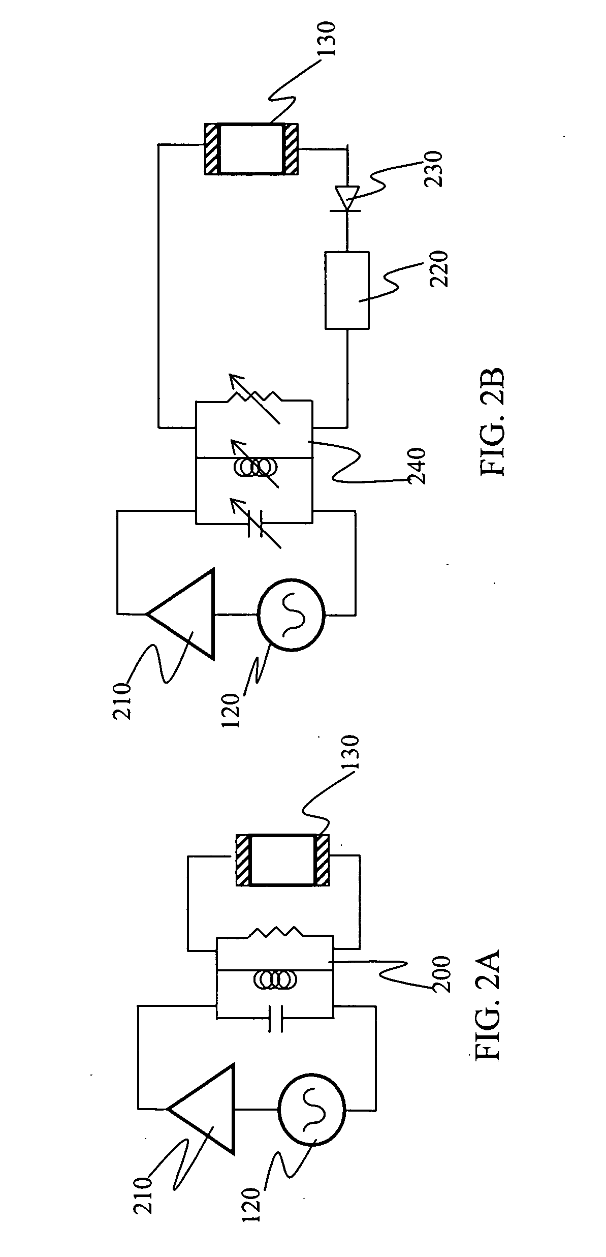
[0014] In yet another aspect, the electromagnetic radiation source is a tunable oscillator, which is tuned to maximize light output.
[0018] In yet another aspect, the electromagnetic resonator is tunable, whereby the electromagnetic resonator is tuned to maximize light output.

Problems solved by technology

Removal of the lamp from the dielectric waveguide body furthermore allows increased light harvesting, a serious drawback of the approaches previously discussed in the art.

Method used


Image

  • External resonator/cavity electrode-less plasma lamp and method of exciting with radio-frequency energy
  • External resonator/cavity electrode-less plasma lamp and method of exciting with radio-frequency energy
  • External resonator/cavity electrode-less plasma lamp and method of exciting with radio-frequency energy

Examples


Embodiment Construction

[0029] The present invention relates to a plasma lamp and, more particularly, to a plasma lamp without electrodes and having a gas-fill vessel that is not contiguous with (detached from) any RF / microwave cavities or resonators. The following description is presented to enable one of ordinary skill in the art to make and use the invention and to incorporate it in the context of particular applications. Various modifications, as well as a variety of uses in different applications will be readily apparent to those skilled in the art, and the general principles defined herein may be applied to a wide range of embodiments. Thus, the present invention is not intended to be limited to the embodiments presented, but is to be accorded the widest scope consistent with the principles and novel features disclosed herein.

[0030] In the following detailed description, numerous specific details are set forth in order to provide a more thorough understanding of the present invention. However, it wi...


PUM


Abstract

Described is a plasma electrode-less lamp. The device comprises an electromagnetic resonator and an electromagnetic radiation source conductively connected with the electromagnetic resonator. The device further comprises a pair of field probes, the field probes conductively connected with the electromagnetic resonator. A gas-fill vessel is formed from a closed, transparent body, forming a cavity. The gas-fill vessel is not contiguous with (detached from) the electromagnetic resonator and is capacitively coupled with the field probes. The gas-fill vessel further contains a gas within the cavity, whereby the gas is induced to emit light when electromagnetic radiation from the electromagnetic radiation source resonates inside the electromagnetic resonator, the electromagnetic resonator capacitively coupling the electromagnetic radiation to the gas, which becomes a plasma and emits light.

Description

PRIORITY CLAIM [0001] The present invention is a non-provisional patent application, claiming the benefit of priority of U.S. Provisional Application No. 60 / 723,144, filed on Oct. 4, 2005, entitled, “External Resonator / Cavity Electrode-less Plasma Lamp and Method of Exciting with Radio-Frequency Energy.”FIELD OF INVENTION [0002] The field of the present invention relates to devices and methods for generating light, more particularly to the field of plasma lamps, and still more particularly to plasma lamps driven by a radio-frequency source without the use of internal electrodes or surrounding dielectric bodies that enhance electromagnetic field coupling. Additionally, the field of the present invention relates to devices and methods where the lamp is not incorporated or a subset of a microwave resonator, a cavity or a waveguide, in particular the lamp and resonator or cavity structure are not geometrically contiguous. BACKGROUND OF INVENTION [0003] Plasma lamps provide extremely bri...

Claims


Application Information

Patent Timeline
IPC IPC(8): H05B41/24
CPCH01J65/042H01J65/046H05B41/2806Y02B20/22Y02B20/00
Inventor ESPIAU, FREDERICK M.MATLOUBIAN, MEHRAN
Owner TOPANGA USA
Why Eureka
Eureka Blog
Learn More