Image display device and simulation device

a display device and simulation device technology, applied in the field of image display devices and simulation devices, can solve the problems of impaired limited size of liquid crystal devices, and not much adopted as game machines or simulation devices, so as to enhance the sense of reality and absorption

Inactive Publication Date: 2007-04-05
NISHI KENJI
View PDF15 Cites 38 Cited by
  • Summary
  • Abstract
  • Description
  • Claims
  • Application Information

AI Technical Summary

Benefits of technology

[0039] In this invention, because the light emitted from the two-dimensional type image forming device is projected and imaged, via the relay optical system, onto the retinas in the right and left eyeballs, with the imaged image being a wide range image having a field of view angle of ±22.5 degrees or more, the image from the two-dimensional type image forming device can be formed in the full field of view angle as actually viewed by human eyes, which enhances the sense of reality and absorption.

Problems solved by technology

However, as a matter of fact, while such devices have been commercialized by a few companies, but have not been much adopted as game machines or simulation devices.
This weight restriction is imposed based on the fact that when the weight exceeds that limit, the user, wearing such display, feels a big load, the sense of reality and absorption is impaired, and the user can wear the display only for a short time.
However, if the weight restriction of from 80 to 500 grammes is imposed, the magnifying lens system and the liquid crystal devices are restricted in their size; thus, such displays as commercially available are generally destined to be an equivalent type of “52-inch huge-sized screen provided 2 m ahead of the user,” i.e., a type of about ±18 degrees in terms of field of view angle.
In this case, however, the user is required to focus the user's eyes on screen 109 provided near the user; and thus, although the user can view the images with a large field of view angle, there is still the disadvantage that the sense of reality and absorption is impaired.
However, although I-MAX provides a considerable effect in that the user can enjoy the sense of reality and absorption, it requires a big space and entails high equipment costs.
Furthermore, when the user turns his face in the right or left direction, the user is to see the auditorium because there is no images in the right and left directions, and thus the user cannot get away from the reality that the user is in a movie theater.
In addition, since the I-MAX facility is large, it is suitable for a game machine for multiple users to appreciate images, but is unsuitable for a game machine to be operated by an individual.
On the other hand, similarly to the I-MAX system, with respect to a device as shown in FIG. 26D, a large space and high equipment costs are required, and, further, as described above, the sense of reality and absorption is impaired in the respect that the user has to focus the user's eyes on images located a few meters ahead of the user, and, still further, there are the following problems.
When the eyes spontaneously follow the movement of the object while, as an image, a remote image located nearly at infinity is displayed, VE sickness is caused, and the user gets sick.
Besides, since almost all of the space has already been utilized as the space for the screen for display and as the space for transmitting the light beams from the projectors, there is, for example, the disadvantage that equipment for giving a sense of reality felt by other sense organs than the eyes is hard to place.

Method used


Image

  • Image display device and simulation device
  • Image display device and simulation device
  • Image display device and simulation device

Examples


Embodiment Construction

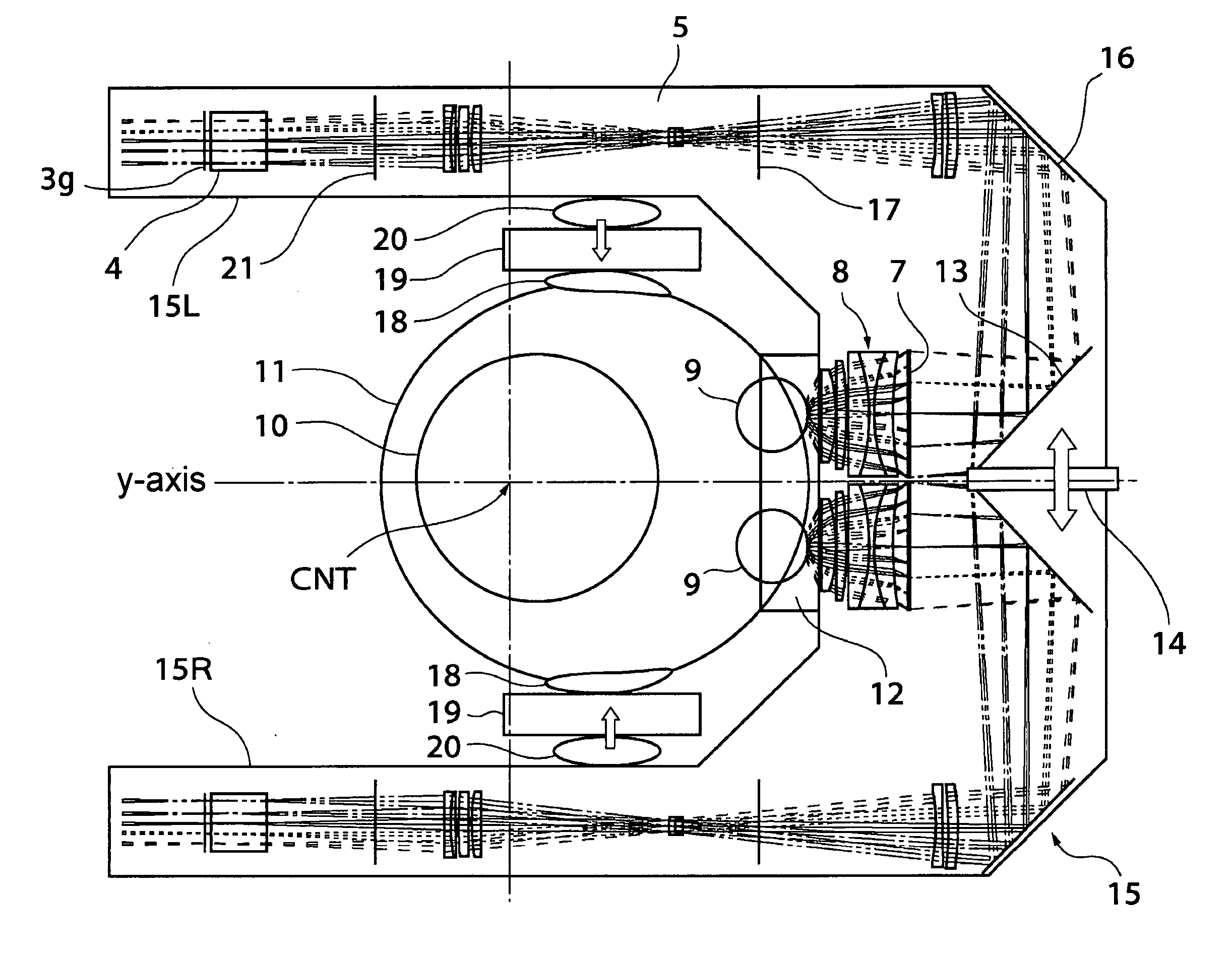
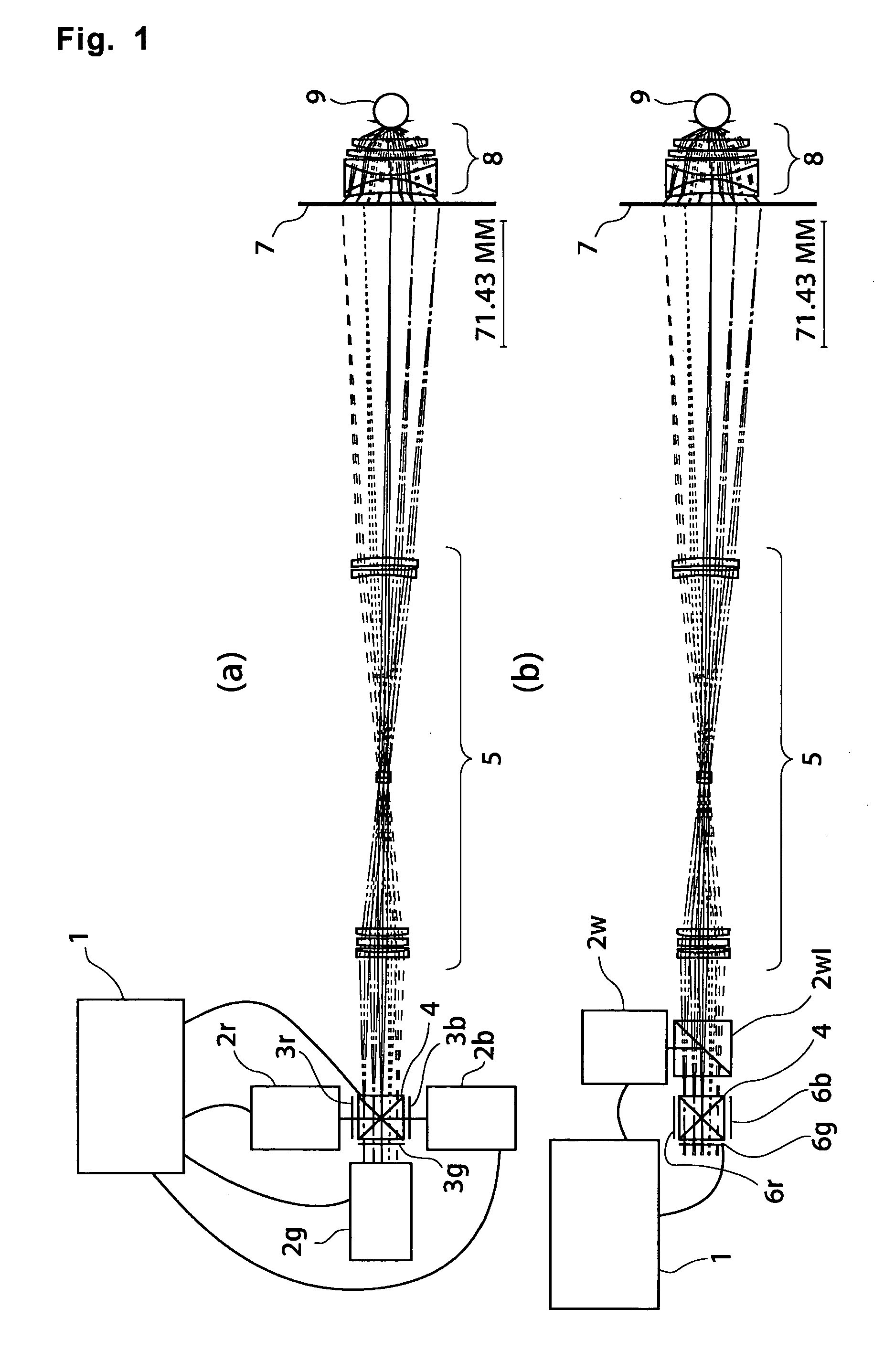
[0122] In the following, examples of the mode for carrying out the present invention will be described, referring to the drawings. In the embodiments of the present invention shown below, an image display device using an eyepiece type magnification optical system similar to that of the image display device shown in FIG. 26B is used. However, because such an image display device system as mounted on the head as shown in FIG. 26B is limited with respect to its weight as described earlier, it is configured such that the image display device is supported by a portion other than the user and thus the image display device is allowed to be heavier.

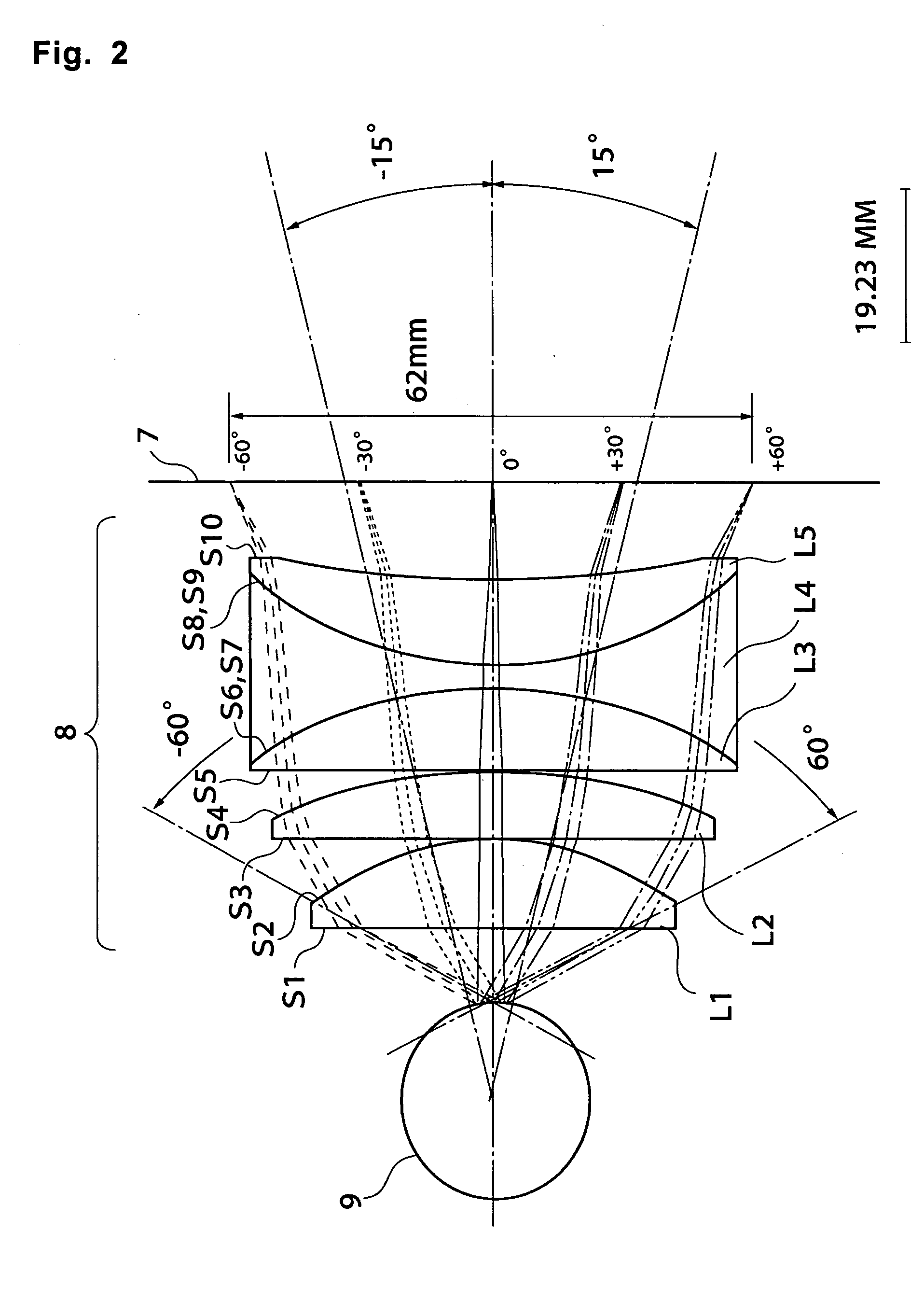
[0123] In addition, because regarding a system in which, like the eyepiece optical system as is generally used in FIG. 26B, a pupil position is located inside the magnification optical system and in which a liquid crystal display device is positioned in a position conjugate with the retina of the eyeball, light beams of which principal ray is in...


PUM


Abstract

Gravity center position GRA of image display device 15 is, in a human state of standing, located in a more backward position compared with eyeball 9 and in a more downward position compared with eyeball 9. In this case, assuming that the rotation axes of the head are the X-axis, the Y-axis, and the Z-axis, the intersection point of these axes is the head's rotational movement center CNT. By this, GRA comes close to CNT, and thus, even when rotational movement of the head occurs around CNT, inertia forces other than moment of inertia are successfully made small. Therefore, the image display device can smoothly follow the movements of human head even if the device is heavy in weight.

Description

TECHNICAL FIELD [0001] The present invention relates to an image display device that is used with it being positioned near to the eyeballs and to a simulation device that uses the image display device. BACKGROUND ART [0002] In FIG. 26A is schematically illustrated a typical game machine that is used in, for example, an arcade and that uses an image display device. On supporting base 101 are placed footstool portion 102 and chair 103; on display stand 104 are mounted display panel 106, wheel 107, and display 105. [0003] The user, sitting on the chair, by operating the wheel 107 in hand, etc. while viewing display 105 and display panel 106, manipulates virtual objects displayed on display 105 to amuse himself or herself, for example. [0004] On the other hand, simulation devices that are typically used for training in how to drive an airplane or a vehicle have a similar configuration to that of the game machine; however, many of the simulation devices are configured such that wheel 107...

Claims


Application Information

Patent Timeline
Patent Type & Authority Applications(United States)
IPC IPC(8): G09G5/00A63B22/06A63F13/211A63F13/25A63F13/28A63F13/52G02B27/00G02B27/01G02B27/02G09B9/058G09B9/30H04N5/64
CPCA63F13/08A63F2300/302A63F2300/8082G02B2027/0178G02B27/0176G02B2027/0132G02B27/0172A63F13/90A63F13/28
Inventor NISHI, KENJI
Owner NISHI KENJI
Why Eureka
Try Eureka