Connector
a technology of connecting rods and connectors, applied in the direction of overvoltage protection resistors, emergency protective arrangements for limiting excess voltage/current, coupling device connections, etc., can solve the problem of not realizing a sufficient characteristic of high-speed signals, and achieve the effect of reducing electrostatic surges, constant input impedance, and reducing electrostatic surges
- Summary
- Abstract
- Description
- Claims
- Application Information
AI Technical Summary
Benefits of technology
Problems solved by technology
Method used
Image
Examples
first embodiment
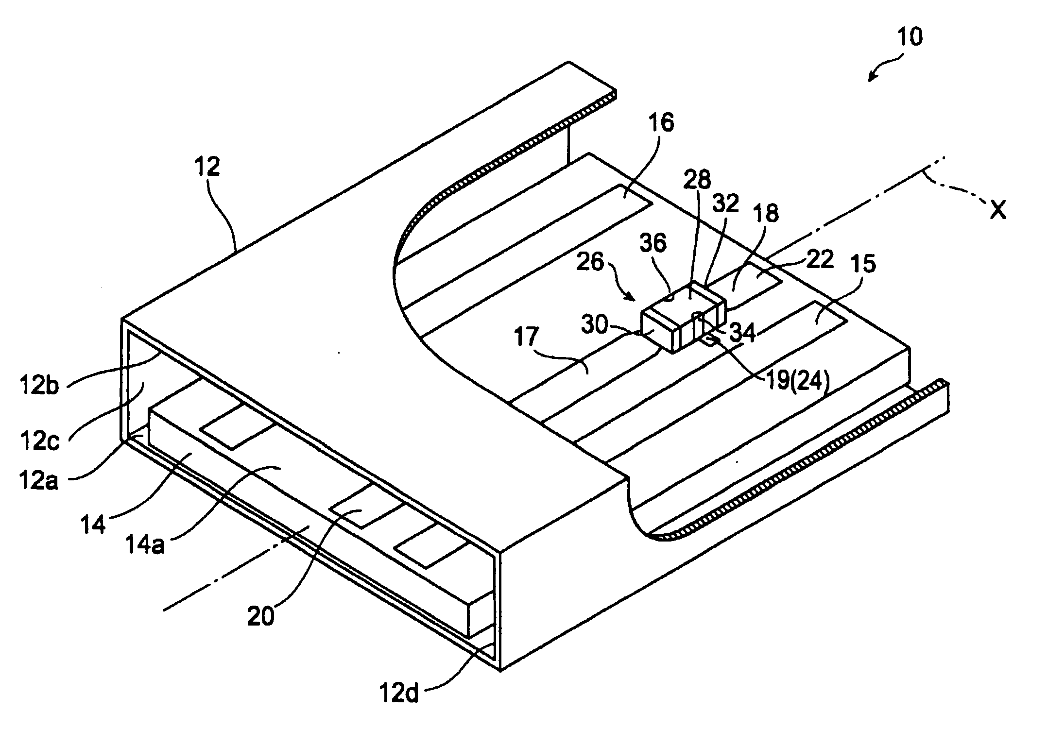
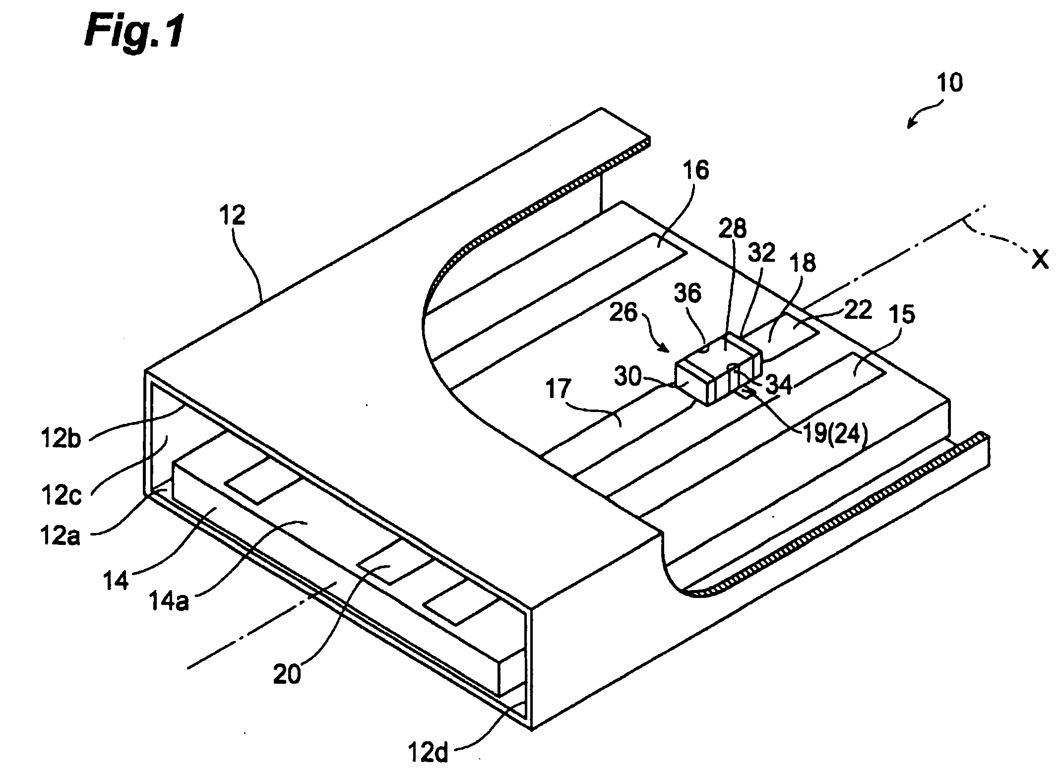
[0059] [First Embodiment]FIG. 1 is a partly broken perspective view showing the connector in accordance with the present invention. This connector 10 comprises a frame 12, a substrate 14, and a multilayer surge absorbing component 26.
[0060] The frame 12 has a rectangular cylindrical form extending along an axis X. Specifically, the frame has inner faces 12a, 12b, 12c, 12d defining an inner hole. The inner faces 12a and 12b are substantially parallel to each other, whereas the inner faces 12c and 12d are substantially parallel to each other. The inner faces 12c and 12d are substantially orthogonal to the inner faces 12a and 12b. The substrate 14 is provided on the inner face 12a of the fame 12.
[0061] The substrate 14 is fixed to the inner face 12a of the frame 12. One main face 14a of the substrate 14 is separated from the inner face 12b. External connectors to connect with the connector 10 are inserted between the substrate 14 and inner face 12b.
[0062] Provided on the main face 14...
example 1
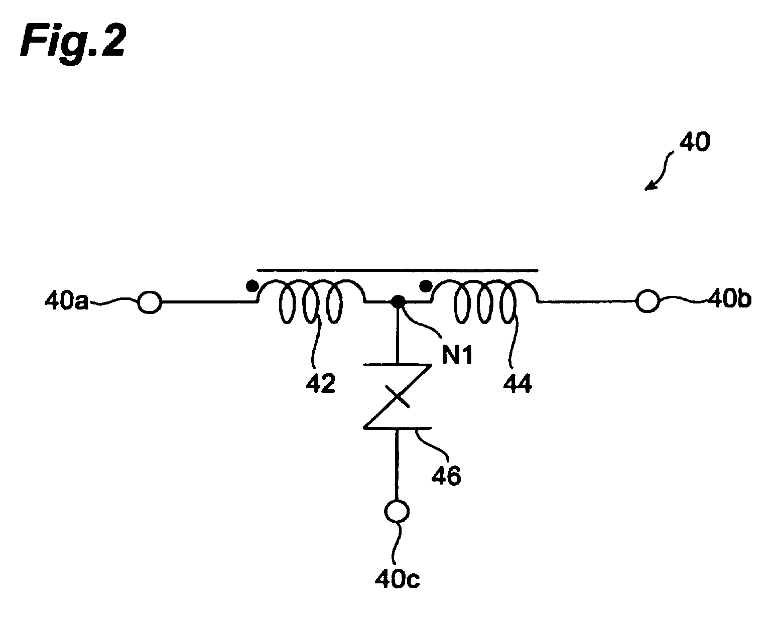
[0079] [Modified Example 1 of surge absorbing circuit employable in the connector of the first embodiment]FIG. 4 is a circuit diagram showing the surge absorbing circuit in accordance with Modified Example 1 employable in the connector of the first embodiment. The surge absorbing circuit 40A shown in FIG. 4 further comprises a first capacitance element 56 in addition to elements similar to those of the surge absorbing circuit 40.
[0080] The first capacitance element 56 has one end connected to a node N3 for connecting the first I / O terminal 40a and one end of the first inductor 42 to each other. The other end of the first capacitance element 56 is connected to a node N4 for connecting the second I / O terminal 40b and the other end of the second inductor 44 to each other.
[0081]FIG. 5 is a circuit diagram equivalently illustrating the surge absorbing circuit shown in FIG. 4. As in the surge absorbing circuit 40, the first inductor 42 and second inductor 44 that are electromagnetically ...
example 3
[0149] [Modified Example 3 of surge absorbing circuit employable in the connector of the second embodiment]FIG. 15 is a circuit diagram showing the surge absorbing circuit in accordance with Modified Example 3 employable in the connector of the second embodiment. The surge absorbing circuit 86C shown in FIG. 15 further comprises a first capacitance element 116 and a second capacitance element 118 in addition to elements similar to those of the surge absorbing circuit 86B of Modified Example 2.
[0150] The first capacitance element 116 has one end connected to a node N 10 for connecting the first I / O terminal 86a and one end of the first inductor 120 to each other. The other end of the first capacitance element 116 is connected to a node N11 for connecting the second I / O terminal 86b and the other end of the second inductor 122 to each other.
[0151] The second capacitance element 118 has one end connected to a node N12 for connecting the third I / O terminal 86c and one end of the third ...
PUM
 Abstract
Description
Claims
Application Information
 - R&D
- Intellectual Property
- Life Sciences
- Materials
- Tech Scout
- Unparalleled Data Quality
- Higher Quality Content
- 60% Fewer Hallucinations
Browse by: Latest US Patents, China's latest patents, Technical Efficacy Thesaurus, Application Domain, Technology Topic, Popular Technical Reports.
© 2025 PatSnap. All rights reserved.Legal|Privacy policy|Modern Slavery Act Transparency Statement|Sitemap|About US| Contact US: help@patsnap.com


