Rolling element accommodating belt for linear guide apparatus and linear guide apparatus

a technology of rolling element and accommodating belt, which is applied in the direction of bearings, shafts and bearings, bearings, etc., can solve the problems of troublesome and difficult automation, troublesome mounting operation, and difficulty in mounting, and achieve the effect of restricting swing and facilitating mounting of rolling elements

Active Publication Date: 2007-04-05
NSK LTD
View PDF18 Cites 31 Cited by
  • Summary
  • Abstract
  • Description
  • Claims
  • Application Information

AI Technical Summary

Benefits of technology

[0039] This invention has been accomplished in view of the above problems. An object of this invention is to provide a rolling element accommodating belt for a linear guide apparatus, capable of facilitating mounting of rolling elements in the rolling element accommodating belt, restricting swing of the rolling element accommodating belt or its friction with guide grooves, preventing coupling arms of the rolling element accommodating belt from rubbing the side walls of guide grooves and the linear guide apparatus provided with such a rolling element accommodating belt.

Problems solved by technology

This makes the assembling operation troublesome and the automation difficult.
However, such a mounting operation is troublesome and requires skill, which is a factor hindering facilitation of manufacture.
So, the manufacture cannot be still executed easily.
The coupling arms may be also damaged owing to the rubbing.
Thus, like the technique disclosed in JP-B-3299450, swing of the rolling element accommodating belt or friction with the guide grooves may occur, which is a factor hindering the smooth operation of the linear guide apparatus.
Further, since both ends are restricted by the rolling element owing to the concave curved faces formed there, swing of the end can be restricted.
As a result, smooth rolling of this rolling element is hindered so that sliding resistance of the slider will be increased.
So, in resin molding, resin is difficult to reach the thin-wall area and hence a chipped area is likely to occur.
As a result, the shape as designed may not be obtained.
Further, since the thin-wall area is likely to become deformed, when the ball is mounted in the belt holder, crushing or chipping is likely to occur.
As a result, the belt holder and the ball may interfere with each other and so mounting of the ball is made difficult.
Thus, the manufacturing capability of the linear guide apparatus may be deteriorated.
This may deteriorate the workability of the mounting operation.

Method used


Image

  • Rolling element accommodating belt for linear guide apparatus and linear guide apparatus
  • Rolling element accommodating belt for linear guide apparatus and linear guide apparatus
  • Rolling element accommodating belt for linear guide apparatus and linear guide apparatus

Examples


first embodiment

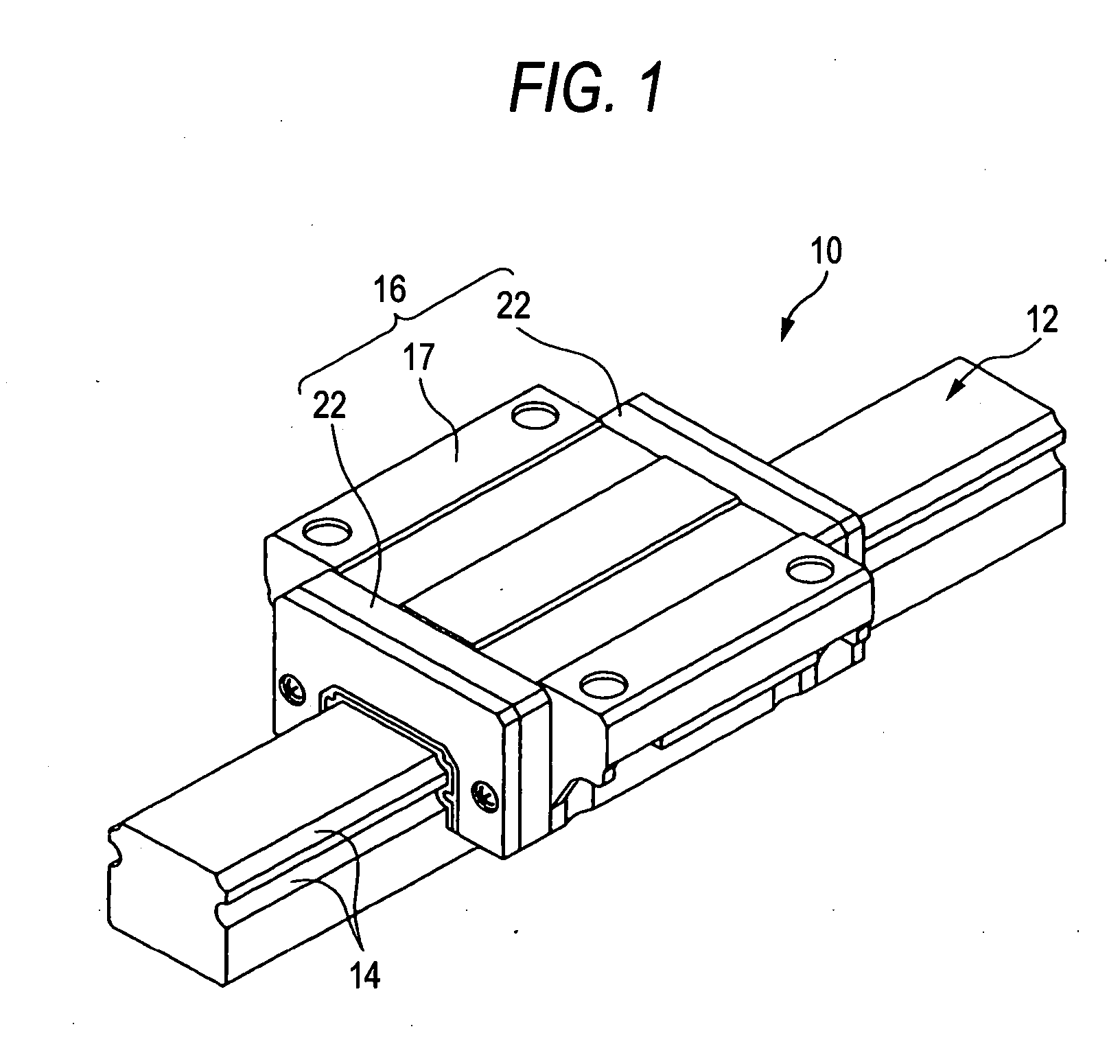
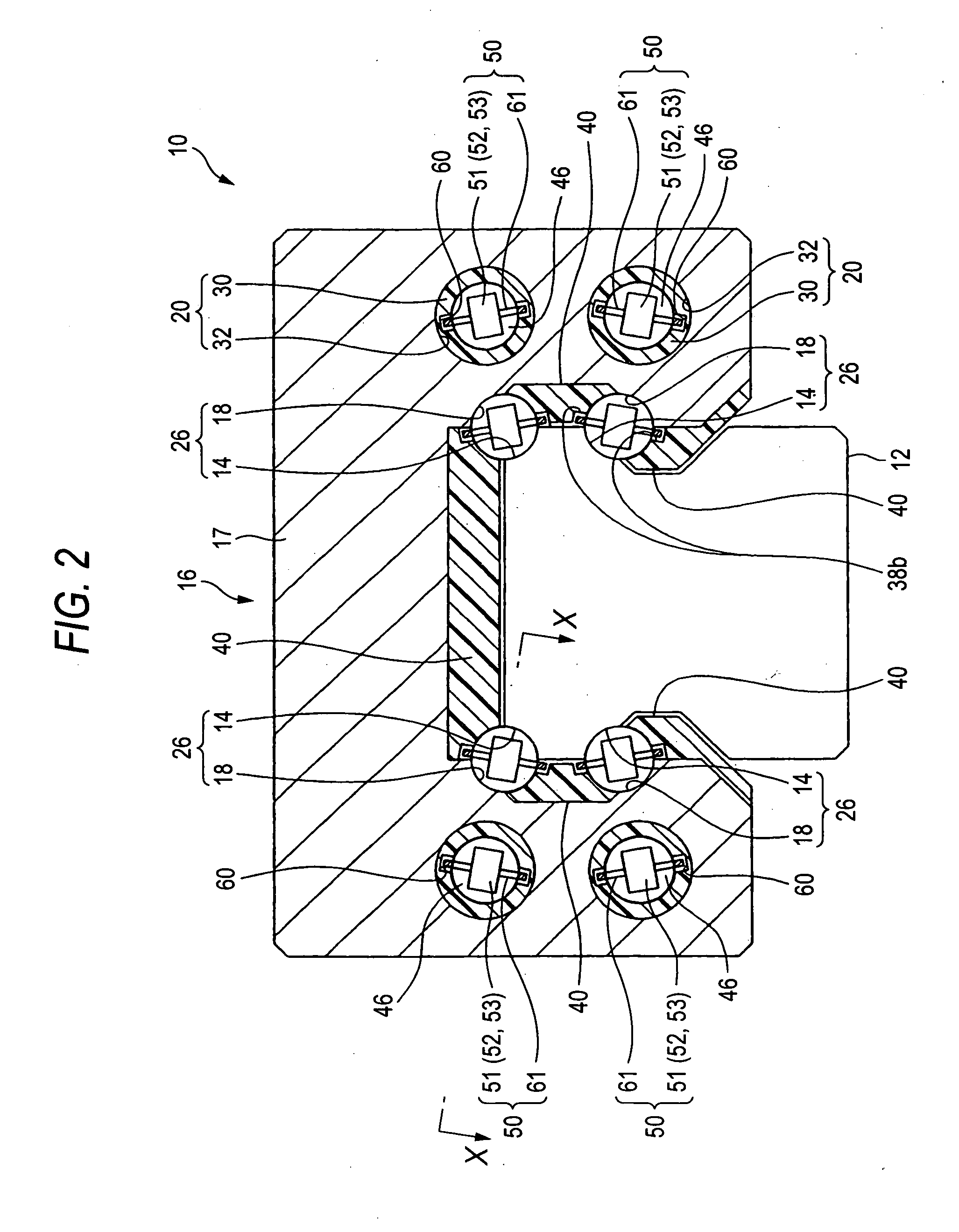
[0287]FIG. 1 is a perspective view of a linear guide according to the first embodiment of a linear guide apparatus provided with a rolling element accommodating belt for use therein according to this invention. FIG. 2 is a view for explaining the cross section of a slider of the linear guide in FIG. 1. FIG. 3 is a sectional view taken in line X-X in the linear guide in FIG. 2.

[0288] As seen from FIGS. 1 and 2, a linear guide apparatus 10 includes a guide rail 12 having rolling element guiding faces 14 and a slider 16 which straddles the guide rail 12 so that the slider is movable relatively to the guide rail 12.

[0289] The guide rail 12 is formed in a square sectional shape, and has four strips of rolling element guiding faces 14, two for each of both sides which are formed linearly in the longitudinal direction.

[0290] The slider 16, as seen from FIG. 1, includes a slider body 17 and end caps 22 mounted at both ends in an axial direction of the slider body 17. The axially continuo...

second embodiment

[0338] Next, an explanation will be given of the linear guide apparatus according to a second embodiment of this invention. In this embodiment, the configuration is the same as the first embodiment except that the structure of the rolling element accommodating belt is partially different. Therefore, only the difference on the rolling element accommodating belt will be explained, and the other will be not be explained.

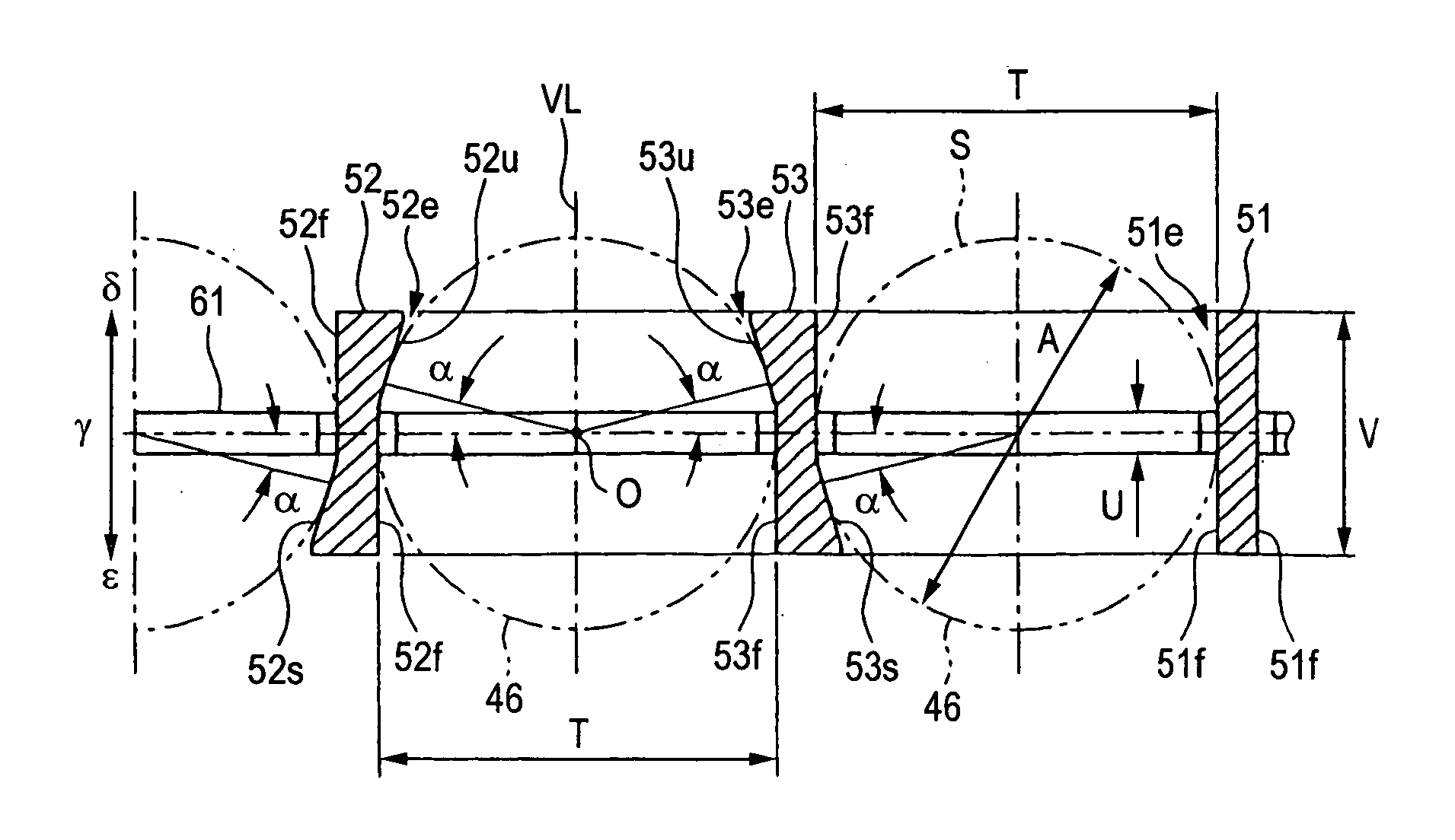
[0339] As seen from FIG. 12, a rolling element accommodating belt 72 has two kinds of spacers, i.e. a spacer 54 and a spacer 55. These spacers are alternately arranged in the arrangement direction of the balls so that two kinds of rolling element accommodating portions, i.e. a rolling element accommodating portion A and a rolling element accommodating portion B are alternately formed in the arrangement direction of the balls 46. The rolling element accommodating belt 50 according to this embodiment is different from that in the first embodiment in that these spacers 54...

third embodiment

[0345] Next, an explanation will be given of the linear guide apparatus according to a third embodiment of this invention. In this embodiment, the configuration is the same as the embodiments described above except that the structure of the rolling element accommodating belt is partially different. Therefore, only the difference on the rolling element accommodating belt will be explained, and the other will be not be explained.

[0346] As seen from FIG. 13, a rolling element accommodating belt 73 is different from the rolling element accommodating belt 50 according to the first embodiment in that it has two kinds of spacers, i.e. a spacer 56 and a spacer 57; and these spacers are alternately arranged in the arrangement direction of the balls so that two kinds of rolling element accommodating portions, i.e. a rolling element accommodating portion A and a rolling element accommodating portion B are alternately formed in the arrangement direction of the balls 46.

[0347] The spacers 56, ...


PUM


Abstract

There is provided a rolling element accommodating belt for a linear guide apparatus which has a guide rail, a slider having a load rolling element guiding face which constitutes a rolling element track path together with the guide rail, a pair of direction converting paths and a rolling element return path, a plurality of rolling elements circulating within an endless circulation path defined by the rolling element track path, the pair of direction converting paths and the rolling element return path; and a guide groove. The rolling element accommodating belt includes a plurality of spacer portions interposed between the rolling elements, coupling arms to be guided by the guide grooves and rolling element accommodating portions accommodating the rolling element. The spacer has an inward abutting face abutting on the rolling element so as to prevent the rolling element from moving to inner diameter side of the endless circulation path.

Description

TECHNICAL FIELD [0001] This invention relates to a rolling element accommodating belt for a linear guide apparatus and the linear guide apparatus equipped with such a rolling element accommodating belt. RELATED ART [0002] Such a kind of linear guide apparatus includes a guide rail having a rolling element guiding face and a slider which is arranged to be movable relatively to the guide rail. The slider has a load rolling element guiding face which constitutes a rolling element track path together with the rolling element guiding face. Further, the slider incorporates a pair of direction converting paths communicating to both ends of the rolling element track path, respectively, and a rolling element return path communicating to the pair of direction converting paths. These rolling element track paths, pair of direction converting paths and rolling element return path constitute an endless circulation path. A plurality of rolling elements circulate within the endless circulation path...

Claims


Application Information

Patent Timeline
Patent Type & Authority Applications(United States)
IPC IPC(8): F16C29/06
CPCF16C29/0638F16C33/3825F16C43/06
Inventor MATSUMOTO, JUNMIZUMURA, YOSHINORI
Owner NSK LTD
Why Eureka
Try Eureka