Electronics device system and electronics device

Inactive Publication Date: 2007-04-05
FUJIFILM HLDG CORP +1
View PDF8 Cites 79 Cited by
  • Summary
  • Abstract
  • Description
  • Claims
  • Application Information

AI Technical Summary

Benefits of technology

[0018] According to the present invention, even if the first electronics device is detached from the second electronics device while recordi

Problems solved by technology

Thus, various problems are caused in disposing the terminal on the mount portion.
Since this technique concerns the terminals having different height, it is impossible to adopt this technique to an uneven shape.
If the le

Method used


Image

  • Electronics device system and electronics device
  • Electronics device system and electronics device
  • Electronics device system and electronics device

Examples


first embodiment

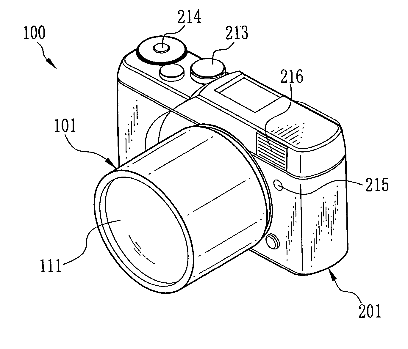
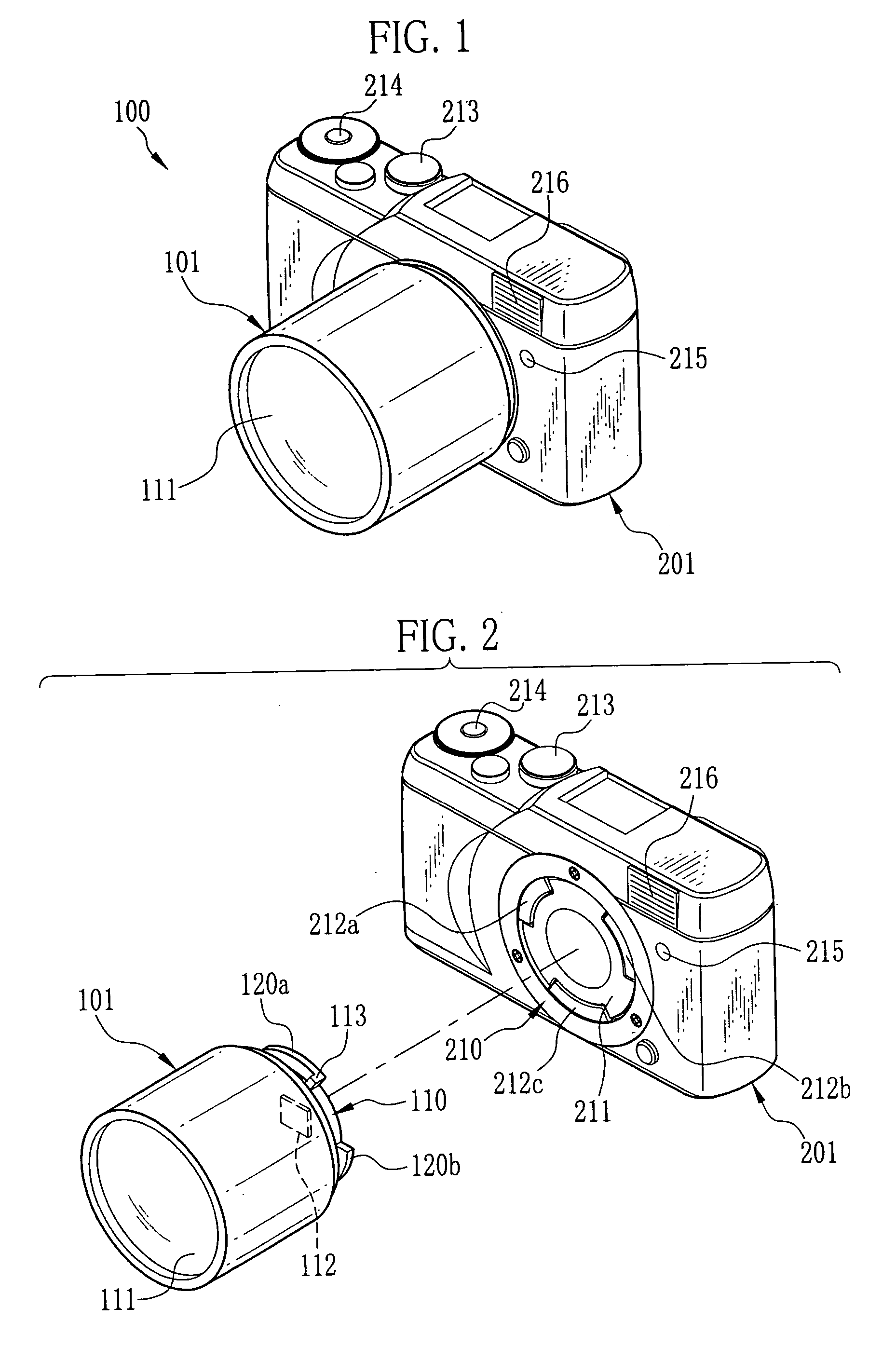
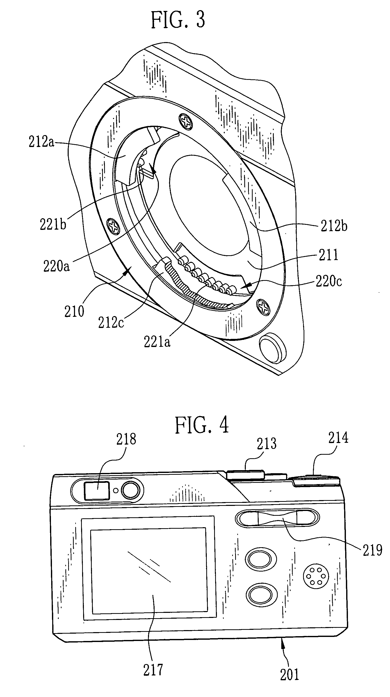
[0036]FIGS. 1 through 4 are perspective views of a camera 100 according to the present invention.

[0037] The camera 100 shown in FIG. 1 is an electronic camera comprising a lens unit 101 and a camera body 201 to which the lens unit 101 is detachably attached. The lens unit 101 includes a shooting optical system 111. The camera body 201 receives image information from the lens unit 101. The lens unit 101 and the camera body 201 are coupled by means of bayonet connection.

[0038]FIG. 2 shows a state in that the lens unit 101 is not yet attached to the camera body 201.

[0039]FIG. 3 shows a mount portion 210 of a body side. The mount portion 210 shown in FIG. 3 is kept in a state that a mount barrier 211 is pushed inside the camera body 201. The mount barrier 211 is biased by a spring or the like from the inside of the camera body 201 toward a front surface thereof.

[0040] As shown in FIG. 2, the center front of the camera body 201 is provided with the body-side mount portion 210 includin...

second embodiment

[0082] In virtue of the terminal 221d, it is possible to make timing of connection and release of the terminals differ in four steps. There are the following effects in addition to the effect identical with the

[0083] For example, in a case that the terminal 221c is used as the GND terminal and the terminal 221d is used as the electric-supply terminal, the GND terminal is connected first in attaching the lens unit 101 to the camera body 201 so that failure to be caused by static electricity is avoided. In addition, when the operation for detaching the lens unit 101 from the camera body 201 is performed, the electric-supply terminal is disconnected after disconnecting all the terminals except for the GND terminal and the electric-supply terminal so that electric connection is stabilized.

third embodiment

[0084] Also in the third embodiment, relative arrangement of the respective terminals 221a, 221b, 221c and 221d is not limited to FIG. 11.

[0085] In the foregoing embodiments described with reference to FIGS. 8 to 11, the connection / release timing is set to two steps, three steps and four steps by changing the intervals of the terminals. The present invention, however, is not limited to the foregoing embodiments as already mentioned in the above. Essentials of the present invention are as follows. The terminals 121a having the terminal width W1 are disposed on the bayonet claw 120a. When the bayonet claw 120a is connected to the bayonet-claw receiver 220a, the specific terminal of the bayonet-claw receiver is disposed at a position separated from a point of the bayonet-claw receiver 220a, with which the center of the terminal 121a overlaps, in the connecting direction or the releasing direction for the purpose of shifting the connection / release timing. When the operation for attachin...


PUM


Abstract

A camera comprises a lens unit and a camera body to which the lens unit is attached by a rotational operation. The camera body is provided with terminals including a specific terminal. Arrangement of the specific terminal is different from that of the other terminals. In detaching the lens unit from the camera body, the specific terminal is adapted to be disconnected earlier relative to the other terminals while the other terminals are connected. After the disconnection of the specific terminal has been detected, the other terminals are set to high impedance.

Description

FIELD OF THE INVENTION [0001] The present invention relates to an electronics device system in which electronics devices of a lens unit and a camera body composing an interchangeable lens camera, for example, are safely detached from each other, and the present invention further relates to the electronics device. BACKGROUND OF THE INVENTION [0002] Conventionally, in a general camera with interchangeable lenses, it is necessary to connect a lens unit and a camera body not only optically but also electrically in order to perform communication and electric supply between them. For this reason, mount portions of the lens unit and the camera body are provided with terminals. The mount portion is restricted regarding its size to some extent. Thus, various problems are caused in disposing the terminal on the mount portion. For the purpose of solving these problems, many inventions concerning the disposition of the terminal have been made. [0003] For example, there is a technique (see Japan...

Claims


Application Information

Patent Timeline
IPC IPC(8): G03B17/00
CPCG03B17/14H04N5/23209H04N2101/00H04N23/663
Inventor TOKIWA, KENTAROMACHIDA, TAKASHI
Owner FUJIFILM HLDG CORP
Why Eureka
Try Eureka