Shaft structure

a shaft and structure technology, applied in the direction of instruments, portable computer details, electric apparatus casings/cabinets/drawers, etc., can solve the problems of high production cost, complex structure, prior art invention, etc., and achieve the effect of simple and versatile shaft structure and significant reduction of production cos

Inactive Publication Date: 2007-04-12
HUANG KUO HUA
View PDF9 Cites 11 Cited by
  • Summary
  • Abstract
  • Description
  • Claims
  • Application Information

AI Technical Summary

Benefits of technology

[0003] The primary objective of the present invention is to provide a shaft structure comprising a pivot shaft, a sleeve barrel and a connecting part. A shaft structure located aside the coupled portion of two objects. The pivot shaft further includes a retaining terminal and a rotary section respectively connected to two objects. The rotary section of the pivot shaft is inserted into the sleeve barrel tightly. Therefore, the shaft structure is simple and versatile, significantly reducing the production cost.

Problems solved by technology

However, the invention of the prior art has the disadvantages of complicated structure and therefore high production cost.
It is a further disadvantage that the shapes of the positioning shaft 10 and the rotary shaft 11 cannot be changed to accommodate objects of various shapes.

Method used


Image

  • Shaft structure
  • Shaft structure
  • Shaft structure

Examples


Embodiment Construction

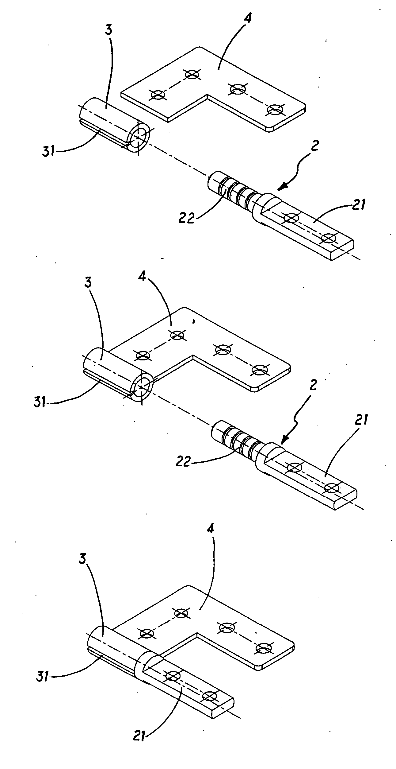
[0029] Referring to FIGS. 3 and 3A, a shaft structure 1 disposed adjacent to the coupled portion of two objects T1 and T2 comprises a pivot shaft 2, a sleeve barrel 3 and a connecting part 4. The pivot shaft 2 further comprises a retaining terminal 21 and a rotary section 22. The retaining terminal 21 is mounted on the object T1. The rotary section 22 is inserted into the sleeve barrel 3; the inner surface of the sleeve barrel 3 further includes an axial slot 31 for retaining the rotary section 22. The connecting part 4 is mounted on the other object T2, and one end of the connecting part 4 is in turn connected around the sleeve barrel 3, being corresponding to a predetermined location opposite to the slot 31. Thereby, the retaining terminal 21 and the connecting part 4 are mounted on the objects Ti and T2, and the rotary section 22 is coupled tightly within the sleeve barrel 3, providing the objects T1 and T2 with relative rotational motion. Further, the tightness between the sleev...


PUM


Abstract

A shaft structure located aside the coupled portion of two objects comprises a pivot shaft, a sleeve barrel and a connecting part. The pivot shaft further includes a retaining terminal and a rotary section. The inner surface of the sleeve barrel is provided with a slot for retaining the rotary section when it is inserted therein, whereby the two objects connected by the retaining terminal and the connecting part may have a relative pivotal motion. Further, the retaining terminal of the shaft and the connecting part may have various shapes according to the objects they are connected with. The tightness between the sleeve barrel and the rotary section can be adjusted to achieve a variety of damping. Therefore, the shaft structure is simple and versatile.

Description

FIELD OF THE INVENTION [0001] The present invention relates shaft structures used in computers and other electronic devices for providing the effects of loosening and rotation so as to attain a preferred pivoting and retaining effect. The present invention has a simple structure comprising only a shaft, a sleeve barrel and a connecting part, which is of low production cost and versatile. BACKGROUND OF THE INVENTION [0002] There are a wide range of applications concerning rotary shafts in computer devices (notebook computers, LCD displays and tablet computers) and in other electronic device (cell phones, translators, PDAs and digital video cameras). A rotary shaft provides pivotal coupling between two objects. In one prior art, as shown in FIGS. 1 and 3, the prior art discloses a positioning shaft 10, a rotary shaft 11 and a torsion unit 12 between the positioning shaft 10 and the rotary shaft 11. The torsion unit 12 comprises a plurality of half-open washers 13 and closed washers 14...

Claims


Application Information

Patent Timeline
Patent Type & Authority Applications(United States)
IPC IPC(8): E05D11/08E05D7/08G06F1/16H05K5/02H05K7/16
CPCE05D3/10E05D11/082E05Y2900/208G06F1/1616Y10T16/54038G06F1/1681H05K5/0226E05Y2900/606G06F1/162
Inventor HUANG, KUO-HUA
Owner HUANG KUO HUA
Why Eureka
Try Eureka