
Vent valve assembly with lever arrangement

a technology of lever arrangement and valve assembly, which is applied in the direction of functional valve types, transportation and packaging, containers, etc., can solve the problems of poor sealing of the valve seal, and achieve the effect of simple and economical manufacture, assembly and us

Inactive Publication Date: 2007-04-12
ALFMEIER CORPORATIO
View PDF48 Cites 24 Cited by
  • Summary
  • Abstract
  • Description
  • Claims
  • Application Information

AI Technical Summary

Benefits of technology

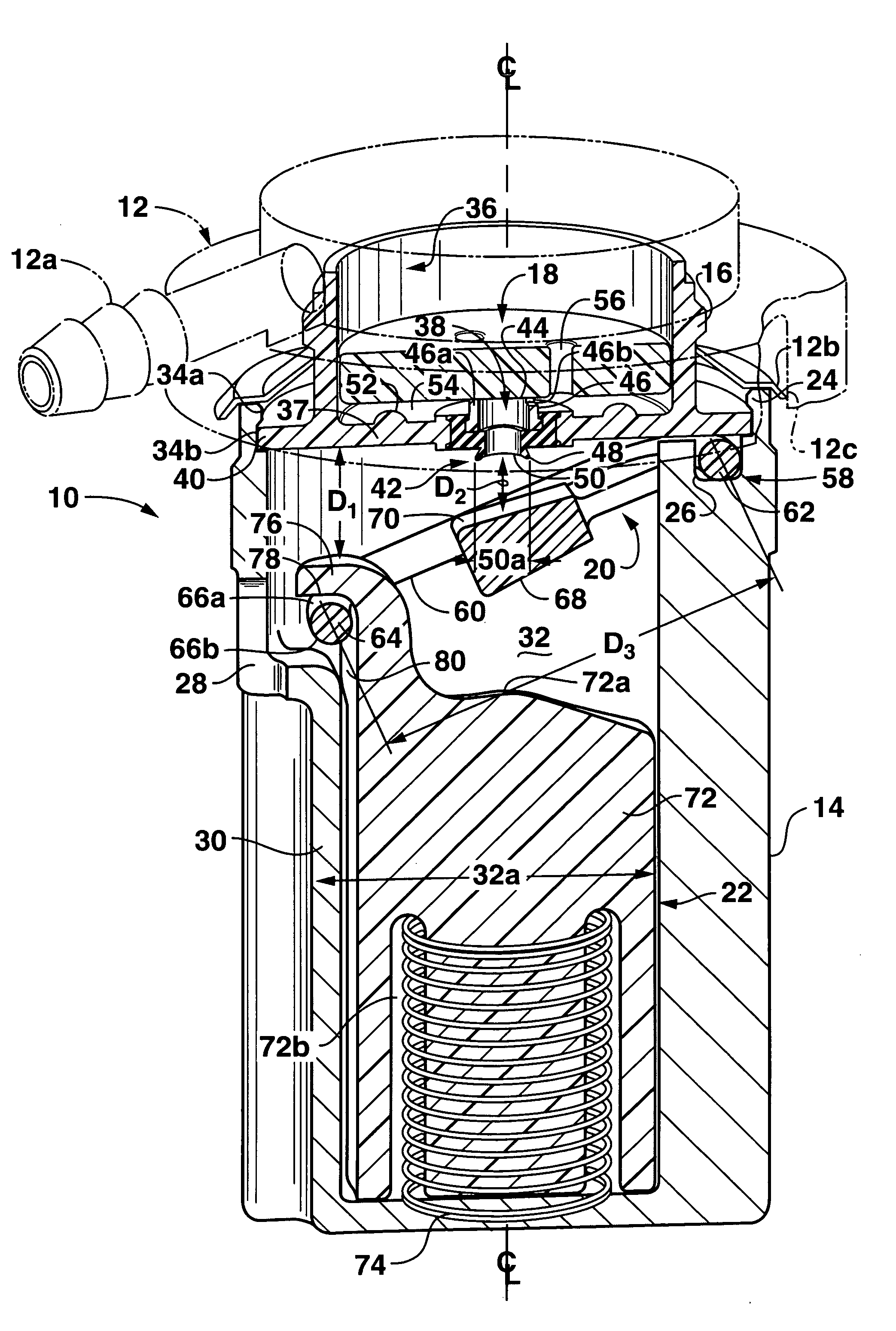
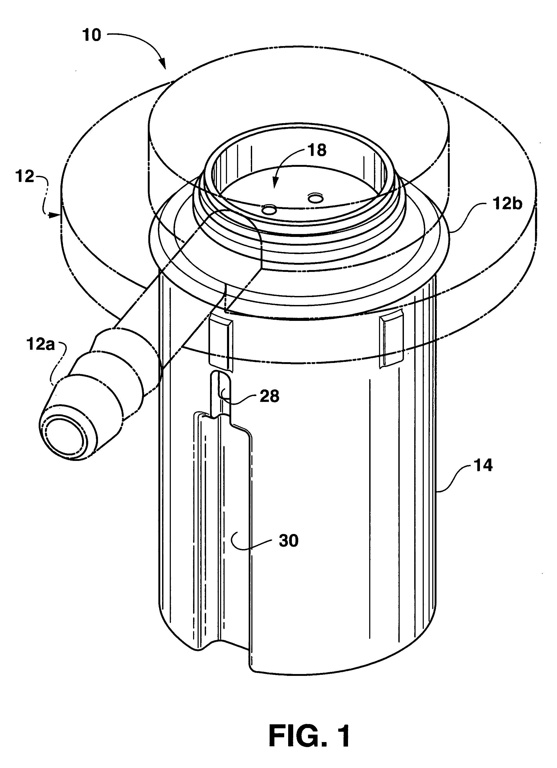
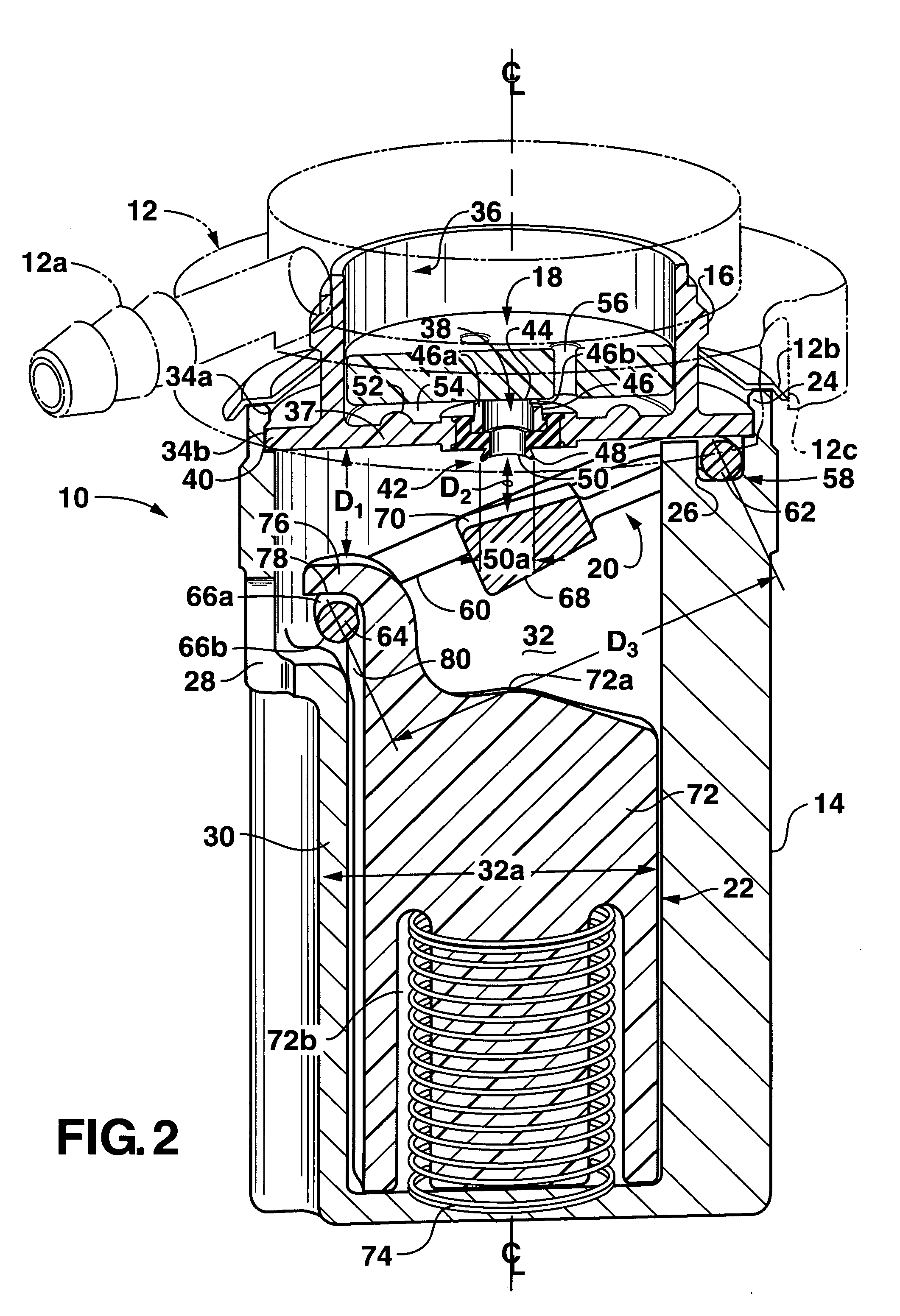
[0008] The present invention provides a lever vent valve (LVV) assembly for a fuel tank of a vehicle that seals a fuel vapor discharge opening in the LVV when the vehicle is on a grade or incline or during a rollover condition to prevent liquid fuel from discharging through the fuel vapor discharge opening in the LVV. Moreover, the LVV assembly reopens after the fuel tank of the vehicle returns to a substantially horizontal position to permit fuel tank venting. The component parts of the LVV assembly are simple and economical to manufacture, assemble, and use. Other advantages of the invention will be apparent from the following description and the attached drawings, or can be learned through practice of the invention.
[0010] In this aspect of the invention, the valve housing defines a plurality of drainage holes, which permit drainage of a liquid fuel accumulated in the chamber in the second vehicle condition to actuate the float such that the sealing surface disengages from about the vapor-inlet opening in the first vehicle condition. In this aspect, a first movement of the float moves the sealing surface in a direction away from the vapor-inlet opening to disengage the sealing surface from about the vapor-inlet opening in the first vehicle condition to permit fuel vapor discharge from the interior and a second movement of the float moves the sealing surface in a direction of the vapor-inlet opening in the second vehicle condition to prevent a liquid fuel from discharging through the vapor-inlet opening and the vapor-outlet opening.
[0014] In another aspect of the invention, a vent valve assembly for attachment in an aperture of a fuel tank wall includes a cap member defining a vapor-inlet opening and a vapor-outlet opening therethrough for selective passage of a fuel vapor from an interior of a fuel tank; a valve housing attachable to the cap member, the valve housing defining a longitudinal axis and a chamber therein and at least partially disposed within the interior of the fuel tank; a float defining a hangar and a catch member, the float being disposed in the chamber of the valve housing and responsive to a first vehicle condition and a second vehicle condition; and a lever arm defining a proximal end, a distal end and a sealing surface therebetween, the proximal end pivotally connected proximate the cap member and the valve housing, a portion of the lever arm proximate the distal end rotatably engaged with the hangar of the float, the hangar of the float configured to move the portion of the lever arm in a direction away from the vapor-inlet opening to disengage the sealing surface from about the vapor-inlet opening in the first vehicle condition to permit the fuel vapor to discharge from the interior of the fuel tank, the catch member configured to move the distal end in a direction of the vapor-inlet opening in the second vehicle condition such that the sealing surface seals the vapor-inlet opening to prevent discharge of a liquid fuel from the interior of the fuel tank. In this aspect, the vapor-inlet opening can be formed about the longitudinal axis of the valve housing, the portion of the lever arm spaced apart from the vapor-inlet opening.
[0021] The valve housing in this aspect has a plurality of drainage holes through it. The drainage holes are configured in the first vehicle condition to drain the liquid fuel accumulated in the chamber during the second vehicle condition to actuate the float such that the sealing surface disengages from about the vapor-inlet opening. In this aspect, the sealing member is spaced apart from the vapor-inlet opening from about 1 mm to about 8 mm in the first vehicle condition, and the proximal end of the lever arm is connected proximate the cap member and the valve housing such that a rotation of the lever assembly limits an axial movement of the float from about 2 mm to about 16 mm in the second vehicle condition.
[0022] In a further aspect of the invention, a vent valve assembly for attachment in an aperture of a fuel tank wall includes a cap member defining a vapor-inlet opening and a vapor-outlet opening therethrough for selective passage of a fuel vapor from an interior of a fuel tank, the vapor-inlet opening defining an outside diameter; a valve housing attachable to the cap member, the valve housing defining a longitudinal axis and a chamber therein and at least partially disposed within the interior of the fuel tank; a float defining a catch member and a hangar depending from proximate the catch member, the float being disposed in the chamber of the valve housing and responsive to a first vehicle condition and a second vehicle condition; and a lever assembly including a lever arm defining a proximal end and a distal end and a sealing device interposed between the proximal end and the distal end, the proximal end rotatably connected proximate the cap member and the valve housing, the sealing device defining a sealing surface thereon, the lever arm and the sealing surface disposed in respective intersecting planes, the lever arm spaced apart from the vapor inlet opening such that the longitudinal axis extends through the sealing device to align the sealing surface with the vapor-inlet opening, the distal end rotatably engaged with the hangar of the float, the hangar of the float configured to move the distal end in a direction away from the vapor-inlet opening to disengage the sealing surface from about the vapor-inlet opening in the first vehicle condition to permit fuel vapor discharge from the interior of the fuel tank, the catch member configured to move the distal end in a direction of the vapor-inlet opening in the second vehicle condition such that the sealing surface becomes substantially parallel to the outside diameter to seal the vapor-inlet opening to prevent fuel vapor discharge from the interior of the fuel tank.

Problems solved by technology

However, the peel-away device may not seal very well due to its flimsy construction.

Method used


Image

  • Vent valve assembly with lever arrangement
  • Vent valve assembly with lever arrangement
  • Vent valve assembly with lever arrangement

Examples


Embodiment Construction

[0035] Detailed reference will now be made to the drawings in which examples embodying the present invention are shown. The detailed description uses numerical and letter designations to refer to features in the drawings. Like or similar designations in the drawings and description have been used to refer to like or similar parts of the invention.

[0036] The drawings and detailed description provide a full and detailed written description of the invention, and of the manner and process of making and using it, so as to enable one skilled in the pertinent art to make and use it, as well as the best mode of carrying out the invention. However, the examples set forth in the drawings and detailed description are provided by way of explanation of the invention and are not meant as limitations of the invention. The present invention thus includes any modifications and variations of the following examples as come within the scope of the appended claims and their equivalents.

[0037] As broad...


PUM


Abstract

A vent valve assembly utilizes a lever arrangement that opens a vapor discharge opening such as during normal operation of a motor vehicle to permit fuel vapor venting and that seals the vapor discharge opening such as when the motor vehicle is inclined to prevent liquid fuel from discharging through the vapor discharge opening.

Description

FIELD OF THE INVENTION [0001] This invention relates to a vent valve assembly for a fuel tank of a motor vehicle. More specifically, the valve assembly utilizes a lever arrangement that selectively opens or closes a vapor discharge opening to permit fuel vapor venting from a vehicle fuel tank or to prevent liquid fuel from discharging through the vapor discharge opening. BACKGROUND OF THE INVENTION [0002] Environmental concerns and governmental regulations require that motor vehicles have fuel management systems that control fuel tank ventilation to reduce emissions of fuel vapors into the atmosphere and that close when the vehicle is inclined or rolls over to prevent a hazardous liquid fuel leak. [0003] Fuel vapor can be created in the fuel tank by temperature differences between the fuel tank and a liquid fuel from a fuel pump, as well as by sloshing and agitation of the fuel in the fuel tank during normal vehicle operation. The pressure buildup resulting from the creation of fuel...

Claims


Application Information

Patent Timeline
Patent Type & Authority Applications(United States)
IPC IPC(8): F16K24/04
CPCF16K24/048Y10T137/3099Y10T137/0777Y10T137/0874
Inventor LEONHARDT, RALF
Owner ALFMEIER CORPORATIO
Learn More