
Electromagnetic coupling device for engine accessories

a technology of electrically-coupling devices and engine accessories, which is applied in the direction of machines/engines, mechanical equipment, etc., can solve the problems of rapid and noticeable torque diversion from powering the engine and transmission, undesirable noise, vibration and harshness, and device attached to the front-end accessory drive (fead) of the engine/motor in the vehicle, so as to enhance engine/vehicle response, performance and fuel economy, and reduce or eliminate power

Inactive Publication Date: 2007-04-12
FORD GLOBAL TECH LLC
View PDF15 Cites 53 Cited by
  • Summary
  • Abstract
  • Description
  • Claims
  • Application Information

AI Technical Summary

Benefits of technology

[0009] The present invention provides a number of advantages. For example, the present invention includes an electromagnetic coupling device having a controllable engagement / disengagement to provide a soft-start / stop capability for an accessory drive, such as a front end accessory drive (FEAD) associated with an internal combustion engine. The ability to operate in a transient slip condition between engagement and disengagement reduces instantaneous power drop (stumble) or power increase (surge) in the engine, as well as reducing noise and vibration during engagement. The soft-start / stop capability for simultaneous coupling / decoupling of multiple engine accessories reduces wear on the clutch and various engine components, such as the drive belt, for example. The ability to simultaneously control engagement / disengagement of the entire FEAD according to the present invention facilitates control strategies that can respond to current ambient and / or operating conditions, modes, or events. Appropriate control of one or more accessory drive clutches each coupled to two or more accessories according to the present invention can temporarily reduce or eliminate the power required to operate all FEAD-driven (and / or other auxiliary drive) devices along with their associated rotational inertia to enhance engine / vehicle response and performance. As such, a smaller engine may be used to obtain similar vehicle launch performance resulting in improved fuel economy. In addition selectively disengaging engine accessories during times of inefficient operation, such as when they are fractionally loaded, and subsequently engaging the accessories when they can operate at higher load and higher efficiency may also contribute to improved fuel economy.

Problems solved by technology

Devices attached to the front-end accessory drive (FEAD) of an engine / motor in a vehicle consume power that could otherwise be directed to motoring the vehicle.
During engagement these clutches use an electrically controlled magnetic field to bring opposing frictional disks or plates into contact, which creates a rapid transfer of angular velocity to the driven clutch plate(s) that may result in undesirable noise, vibration, and harshness.
In addition, the rapid transfer of torque to the engaged device often creates a rapid and noticeable diversion of torque from powering the engine and transmission.
In addition, wearing of the frictional surfaces during engagement will eventually reduce the torque transfer capacity of the device.

Method used


Image

  • Electromagnetic coupling device for engine accessories
  • Electromagnetic coupling device for engine accessories
  • Electromagnetic coupling device for engine accessories

Examples


Embodiment Construction

)

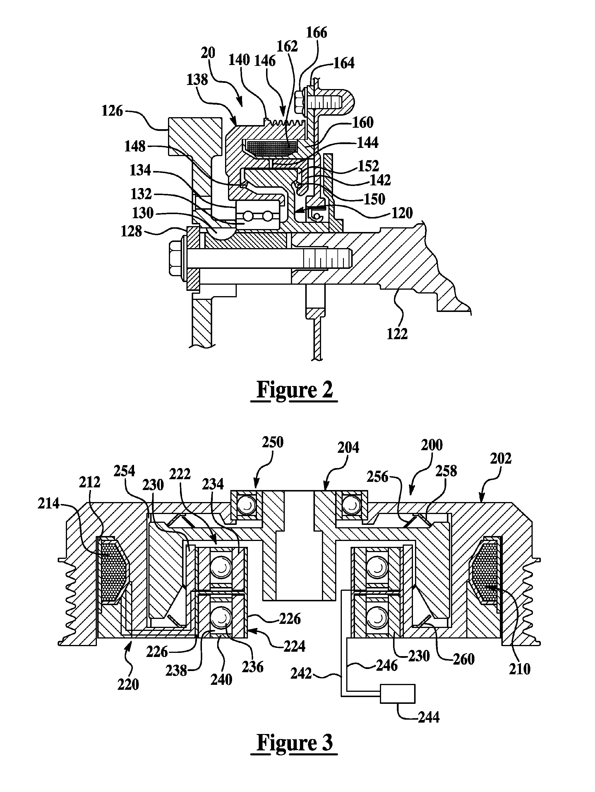
[0016] As those of ordinary skill in the art will understand, various features of the present invention as illustrated and described with reference to any one of the Figures may be combined with features illustrated in one or more other Figures to produce embodiments of the present invention that are not explicitly illustrated or described. The combinations of features illustrated provide representative embodiments for typical applications. However, various combinations and modifications of the features consistent with the teachings of the present invention may be desired for particular applications or implementations.

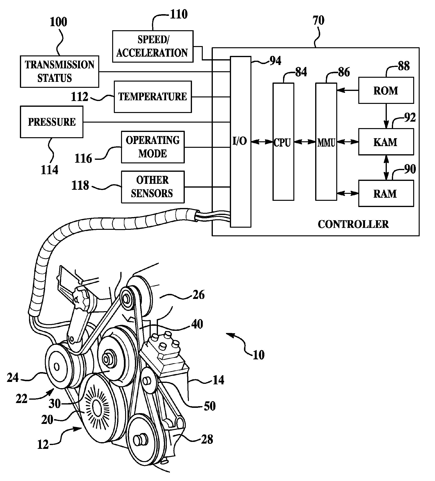
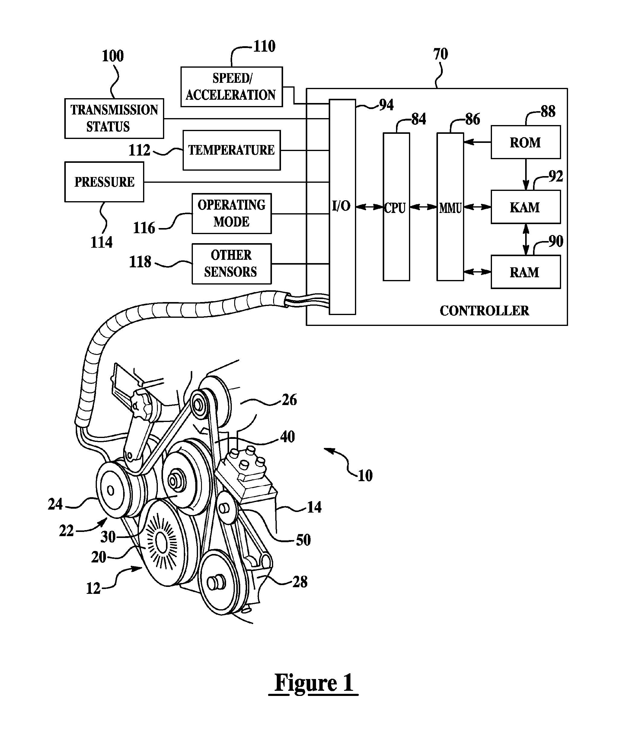
[0017]FIG. 1 illustrates a representative automotive application of one embodiment for a system and method for controlling engine accessories according to the present invention. As illustrated in FIG. 1, system 10 includes a front-end accessory drive (FEAD) 12 connected to a multiple cylinder internal combustion engine 14, only a portion of which is shown. While illu...


PUM


Abstract

A system and method for controlling a plurality of accessories associated with a multiple cylinder internal combustion engine having the accessories coupled to an engine crankshaft by an electromagnetic coupling device with a flowable magnetic material disposed between a driving member and a driven member include selectively supplying power to the electromagnetic coupling device in response to at least one operating condition to simultaneously engage or disengage the plurality of engine accessories. Embodiments include a magnetic particle clutch or magnetorheological fluid clutch connected to an engine crankshaft and a plurality of engine accessories that may include an air conditioning compressor, water pump, power steering pump, alternator, and / or supercharger, for example.

Description

BACKGROUND OF THE INVENTION [0001] 1. Field of the Invention [0002] The present invention relates to systems and methods for coupling accessories to an engine / motor. [0003] 2. Background Art [0004] Devices attached to the front-end accessory drive (FEAD) of an engine / motor in a vehicle consume power that could otherwise be directed to motoring the vehicle. Typical accessories may include a power steering pump, water pump, alternator, air conditioning compressor, air compressor, power-take off (PTO) drive, air for an induction blower, or a supercharger, for example. Various engine / motor accessories may be engaged / disengaged based on a request from the vehicle operator and / or the engine / vehicle controller in response to current ambient and vehicle operating conditions. However, each device is generally controlled independently of the state of other devices. [0005] In automotive applications, electromagnetic friction clutches are often used to selectively engage various belt-driven FEA...

Claims


Application Information

Patent Timeline
IPC IPC(8): F02B67/06F16D37/02
CPCF02B67/06F16D37/008
Inventor LARRY, ELIEGINDER, JOHNMARANVILLE, CLAYPUGLIESE, LUISBEABER, WALLY
Owner FORD GLOBAL TECH LLC
Learn More