High efficiency buck converter for both full load and light load operations

Active Publication Date: 2007-04-12
SEMICON COMPONENTS IND LLC
View PDF5 Cites 102 Cited by
  • Summary
  • Abstract
  • Description
  • Claims
  • Application Information

AI Technical Summary

Benefits of technology

[0011] It is an object of the present invention to provide a buck converter having power

Problems solved by technology

Notwithstanding, the synchronous rectifying operation can improve the efficiency of the buck converter at heavy load condition but fails to overcome low efficiency at light load condition, which is caused by a backward discharging phenomenon.
An

Method used


Image

  • High efficiency buck converter for both full load and light load operations
  • High efficiency buck converter for both full load and light load operations
  • High efficiency buck converter for both full load and light load operations

Examples


Embodiment Construction

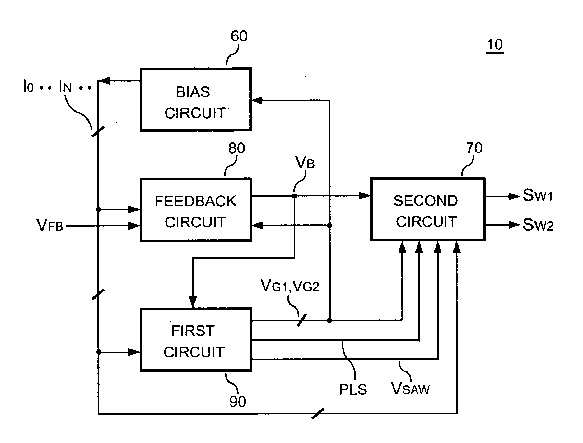
[0026]FIG. 6 shows a block diagram of a control circuit 10 of a buck converter according to an embodiment of the present invention. The control circuit 10 comprises a bias circuit 60, a feedback circuit 80, a first circuit 90, and a second circuit 70. The bias circuit 60 produces bias currents, IO . . . IN, for circuits of the buck converter. A voltage divider formed by resistors 51 and 52 is coupled from the output of the buck converter to a ground reference level for generating a signal VFB, which is proportional to the output voltage VO of the buck converter, to the feedback circuit 80. The feedback circuit 80 further generates a feedback signal VB in response to the signal VFB, which represents the load conditions. The first circuit 90 generates an oscillation signal PLS, a saw-tooth signal VSAW, a power-saving signal VG1, and an auxiliary control signal VG2.

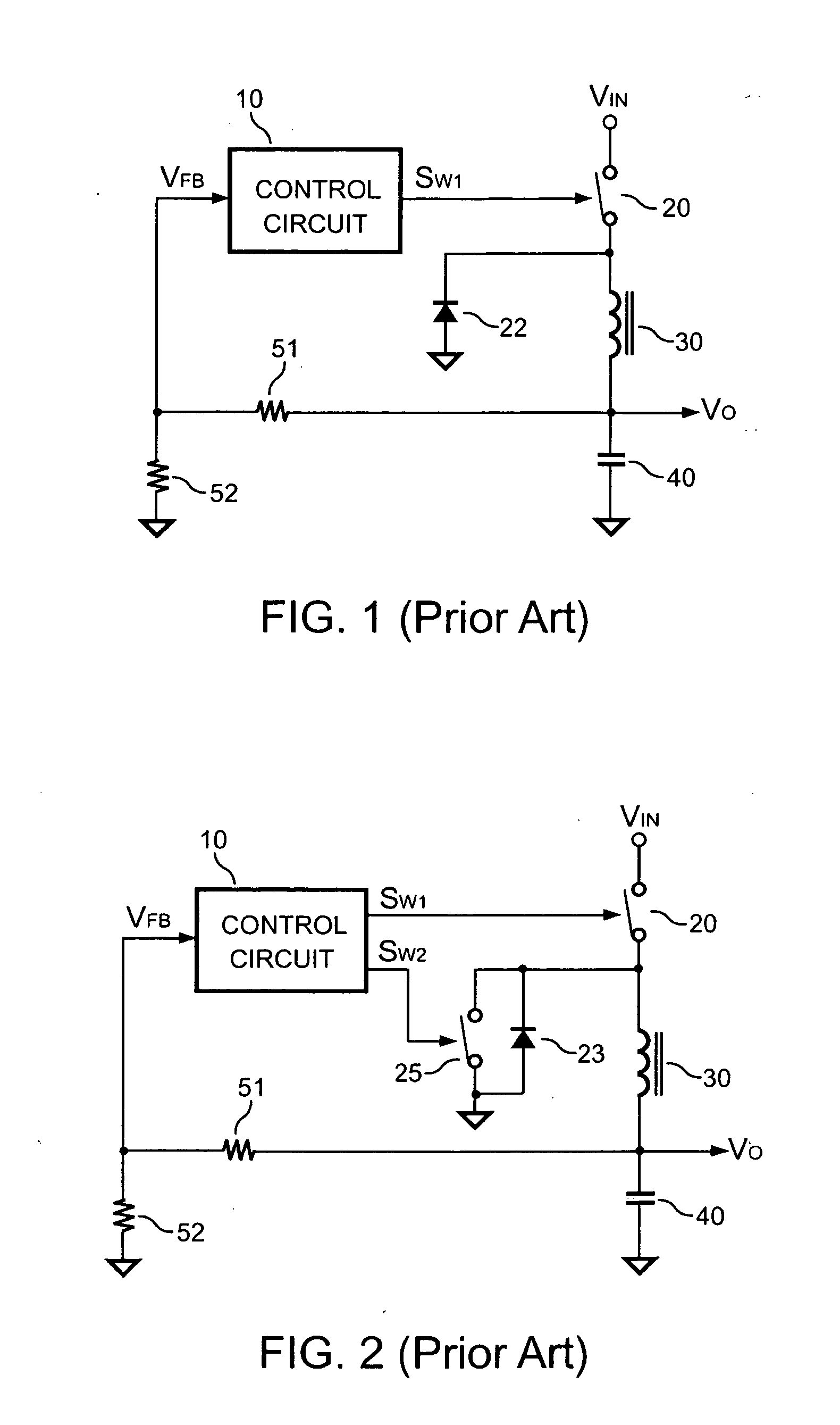
[0027] Referring to FIG. 2 and FIG. 6, the second circuit 70 generates a main switching signal SW1 and a secondary switch...


PUM


Abstract

A high efficiency buck converter has power-saving means to improve the efficiency under both heavy load and light load conditions. A first circuit generates an oscillation signal and a power-saving signal in response to a feedback signal. In reference to the feedback signal and the oscillation signal, a second circuit generates switching signals to control switching devices. An off-time of the switching signal increases in response to a decrement of load. The power-saving signal turns off the switching devices and parts of control circuits of the buck converter during the off-time of the switching signal for saving power under light load conditions.

Description

BACKGROUND OF THE INVENTION [0001] 1. Field of the Invention [0002] The present invention relates to buck converters, switching regulators and power converters. [0003] 2. Description of Related Art [0004] In applications for computers, communication and consumer products, buck converters are widely applied to provide regulated output voltages such as 3.3V, 2.5V, 1.8V, 0.9V etc. from a higher input voltage, such as 12V. Among these applications, PWM (pulse width modulation) is a switching technology mainly used. In addition, a synchronous rectifying technology is applied to improve the efficiency of buck converters under heavy load conditions. [0005]FIG. 1 shows a conventional buck converter. A switch 20 is coupled to an input voltage VIN of the buck converter. With the operation of the switch 20, the power of the input voltage VIN will be converted to an output voltage VO via an inductor 30. A voltage divider formed by resistors 51 and 52 is coupled from the output voltage VO of the...

Claims


Application Information

Patent Timeline
IPC IPC(8): G05F1/00
CPCH02M3/1588H02M2001/0032Y02B70/1466Y02B70/16H02M1/0032Y02B70/10
Inventor YANG, TA-YUNG
Owner SEMICON COMPONENTS IND LLC
Why Eureka
Try Eureka