Light scanning device and scanning optical system

Inactive Publication Date: 2007-04-12
ASAHI KOGAKU KOGYO KK
View PDF12 Cites 10 Cited by
  • Summary
  • Abstract
  • Description
  • Claims
  • Application Information

AI Technical Summary

Benefits of technology

[0008] The present invention is advantageous in that there can be provided an improved light scanning device and an improved scanning optical system that are configured to reduce a jitter amount in an auxiliary scanning direction without making the size of a polygon mirror smaller.
[0015] According to a further aspect of the present invention, there is provided a light scanning device, which includes: a polygon mirror configured to be rotatable around a predetermined rotation axis to reflect and deflect an incident light beam with a plurality of reflecting surfaces thereof; a light source configured to emit at least one light beam and make the at least one light beam emitted incident onto the polygon mirror from an outside of a scanning range of the at least one light beam being scanned in a main scanning direction by the polygon mirror; and an image forming optical system configured to converge the at least one light beam deflected by the polygon mirror as a spot scanned in the main scanning direction on a scanned object surface. A position on each of the plurality of reflecting surfaces at which a chief ray of the at least one light beam intersects with each of the plurality of reflecting surfaces is adjusted such that a jitter amount in an auxiliary scanning direction perpendicular to the main scanning direction can be reduced over the scanning range on the scanned object surface.
[0016] According to a further aspect of the present invention, there is provided a scanning optical system, which includes: a polygon mirror configured to be rotatable around a predetermined rotation axis to reflect and deflect an incident light beam with a plurality of reflecting surfaces thereof; a light source configured to emit at least one light beam and make the at least one light beam emitted incident onto the polygon mirror from an outside of a scanning range of the at least one light beam being scanned in a main scanning direction by the polygon mirror; and an image forming optical system configured to converge the at least one light beam deflected by the polygon minor as a spot scanned in the main scanning direction on a scanned object surface. A position on each of the plurality of reflecting surfaces at which a chief ray of the at least one light beam intersects with each of the plurality of reflecting surfaces is adjusted such that a jitter amount in an auxiliary scanning direction perpendicular to the main scanning direction can be reduced over the scanning range on the scanned object surface.

Problems solved by technology

However, it is difficult to attain the polygon mirror with each of the reflecting surfaces perfectly parallel to the rotation axis, and each of the reflecting surfaces of the polygon mirror generally has a certain level of tilt angle between the rotation axis and itself due to various kinds of manufacturing errors.
Meanwhile, the line image cannot be formed just on each of the reflecting surfaces of the polygon mirror at each of the other rotational positions.
Accordingly, in the case of the optical face tangle error, the spot location on the scanned object surface in the auxiliary scanning direction is shifted depending on that in the main scanning direction, and thereby a scanned line that should ideally be straight is improperly curved.
Therefore, the jitter amount is very large at the end opposite to the light source side end, so that a drawing performance is worsened.
Namely, in this technique, it is needed for ensuring a certain level of scanning range to reduce the number of the reflecting surfaces, yet it makes it difficult to heighten a drawing speed.

Method used


Image

  • Light scanning device and scanning optical system
  • Light scanning device and scanning optical system
  • Light scanning device and scanning optical system

Examples


Embodiment Construction

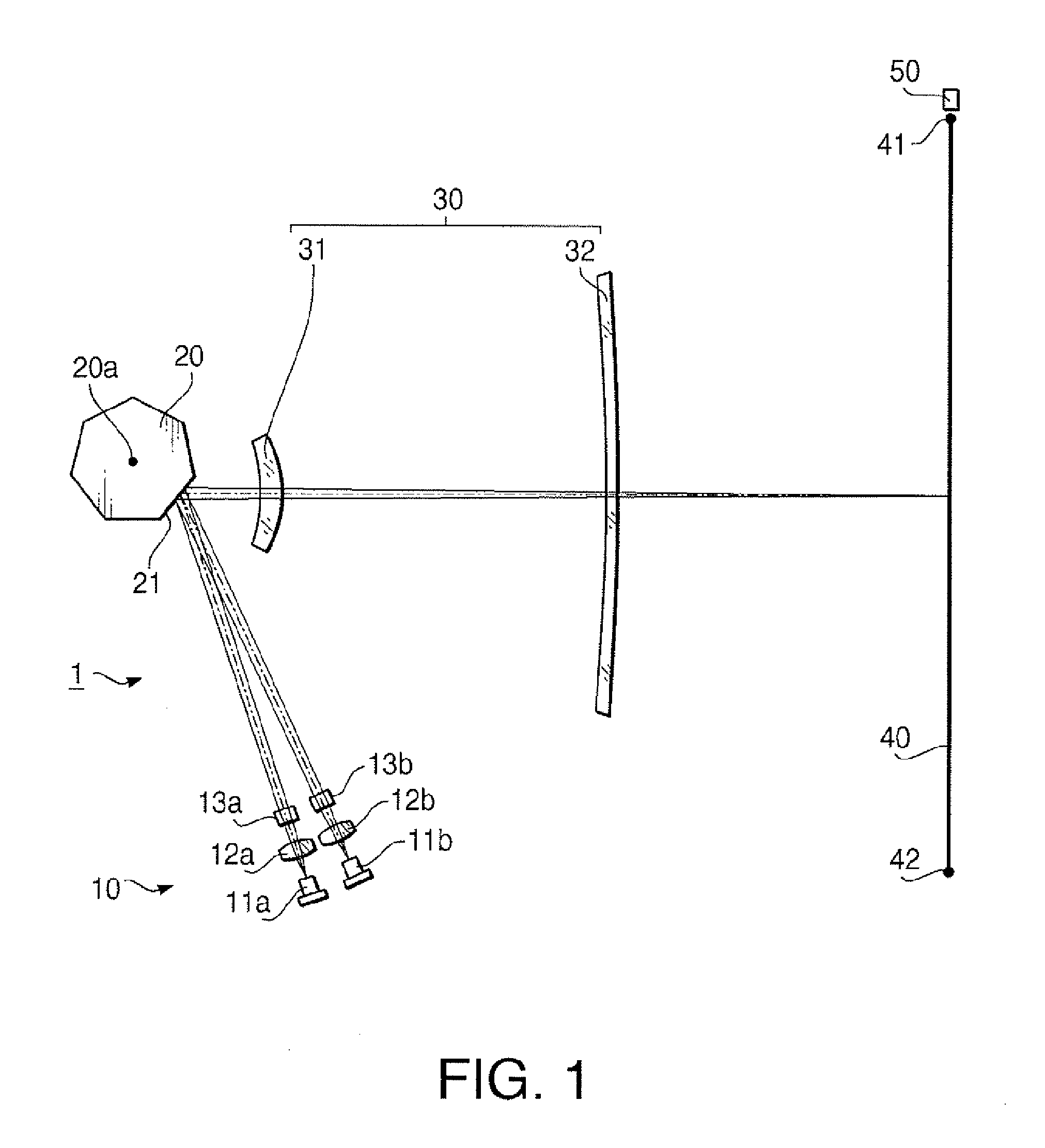
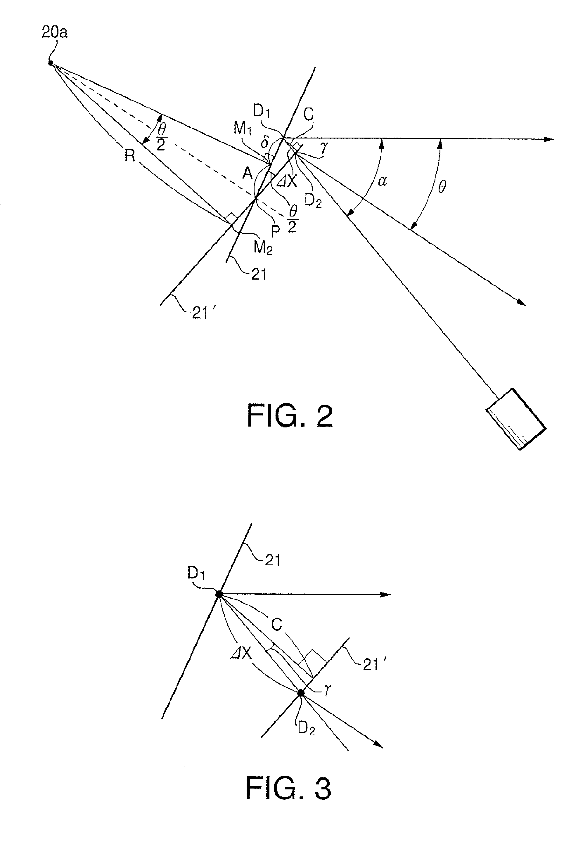
[0023] Hereinafter, embodiments of a light scanning device (scanning optical system) according to the present invention will be explained with reference to the accompanying drawings.

[0024] A light scanning device in an embodiment, which is used as a laser scanning unit (LSU) of the laser printer, is configured to scan a laser beam that is ON / OFF modulated in accordance with an inputted drawing signal on a scanned object surface such as a photoconductive drum and form an electrostatic latent image. In this specification, a direction in which a spot is scanned on the scanned object surface is defined as a main scanning direction, and a direction perpendicular to the main scanning direction is defined as an auxiliary scanning direction. In addition, explanations about directions of a shape and power of each optical element will be made based on the directions on the scanned object surface. A plane that is parallel to the main scanning direction and includes an optical axis of an image...


PUM


Abstract

A light scanning device includes a polygon mirror configured to be rotatable around a rotation axis to reflect and deflect a light beam with a plurality of reflecting surfaces, a light source that makes a light beam incident onto the polygon mirror from an outside of a scanning range of the light beam being scanned in a main scanning direction by the polygon mirror, and an image forming optical system that converges the deflected light beam as a spot scanned in the main scanning direction on a scanned surface. In a state where the light beam is directed to a center of the scanning range on the scanned surface, a chief ray of the light beam intersects with a reflecting surface at a point shifted by a predetermined amount in a direction toward a side opposite the light source front a center of the reflecting surface in the main scanning direction.

Description

BACKGROUND OF THE INVENTION [0001] The present invention relates to a light scanning device and a scanning optical system incorporated in a laser printer or the like that are configured to scan a laser beam on a scanned object surface, in particular, a light scanning device and a scanning optical system configured to reduce jitter in an auxiliary scanning direction. [0002] A light scanning device (scanning optical system) incorporated in a laser printer or the like is configured such that a laser beam emitted from a light source is reflected and deflected by a deflector such as a polygon mirror, and is directed onto a scanned object surface such as a photoconductive drum via a scanning lens such as an fθ lens to provide an image as a spot thereon. The spot on the photoconductive drum is scanned in a main scanning direction accompanied by the rotation of the polygon mirror. At this time, an electrostatic latent image is formed on the scanned object surface with the laser beam being O...

Claims


Application Information

Patent Timeline
IPC IPC(8): G02B26/08
CPCG02B26/123G02B26/124H04N1/113H04N2201/04796
Inventor MATSUOKA, SHOHEI
Owner ASAHI KOGAKU KOGYO KK
Why Eureka
Try Eureka