Scanning optical system

Active Publication Date: 2005-08-30
ASAHI KOGAKU KOGYO KK
View PDF9 Cites 11 Cited by
  • Summary
  • Abstract
  • Description
  • Claims
  • Application Information

AI Technical Summary

Benefits of technology

[0030]The present invention is advantageous in that it provides a scanning optical system which is capable of reducing the jitter amount in the auxiliary scanning direction caused in connection with the change of the deflection point and the facet error.
[0038]In a particular case, the imaging optical system may have two lenses. With this structure, the lateral magnification of the imaging optical system in the auxiliary scanning direction can be reduced, and therefore the jitter amount can be effectively reduced.
[0039]In a particular case, refractive power in an auxiliary scanning plane of a lens surface of the imaging optical system located nearest to the scan target surface may be the largest of all lens surfaces of the imaging optical system. The auxiliary scanning plane is a plane which includes an optical axis of the imaging optical system and which is perpendicular to the main scanning direction. With this structure, the lateral magnification of the imaging optical system in the auxiliary scanning direction can be reduced, and therefore the jitter amount can be effectively reduced.

Problems solved by technology

However, to make all of the reflective surfaces of the polygonal mirror exactly parallel with the rotational axis thereof during manufacturing process of the polygonal mirror is impossible.
The variations of the jitter amount deteriorate imaging quality.
However, there is a case where the jitter amount of the conventional scanning optical system exceeds the permissible jitter amount of 5.0 μm.
However, the error of the polygonal mirror discussed in this publication is a manufacturing error of the polygonal mirror with regard to the distance between the rotational axis and each reflective surface.
As described above, a problem caused by the phenomenon of the change of the deflection point (i.e., the variations of the jitter amounts) has not been resolved.
However, a polygonal mirror manufactured using a typical manufacturing process usually has the facet error of about 180″ (=0.00087 rad).
To manufacture a polygonal mirror having precision higher than that of the polygonal mirror manufactured using the typical manufacturing process (i.e., to manufacture a polygonal mirror having the facet error less than 180″) considerably increases the manufacturing cost of the polygonal mirror.

Method used


Image

  • Scanning optical system
  • Scanning optical system
  • Scanning optical system

Examples


first example

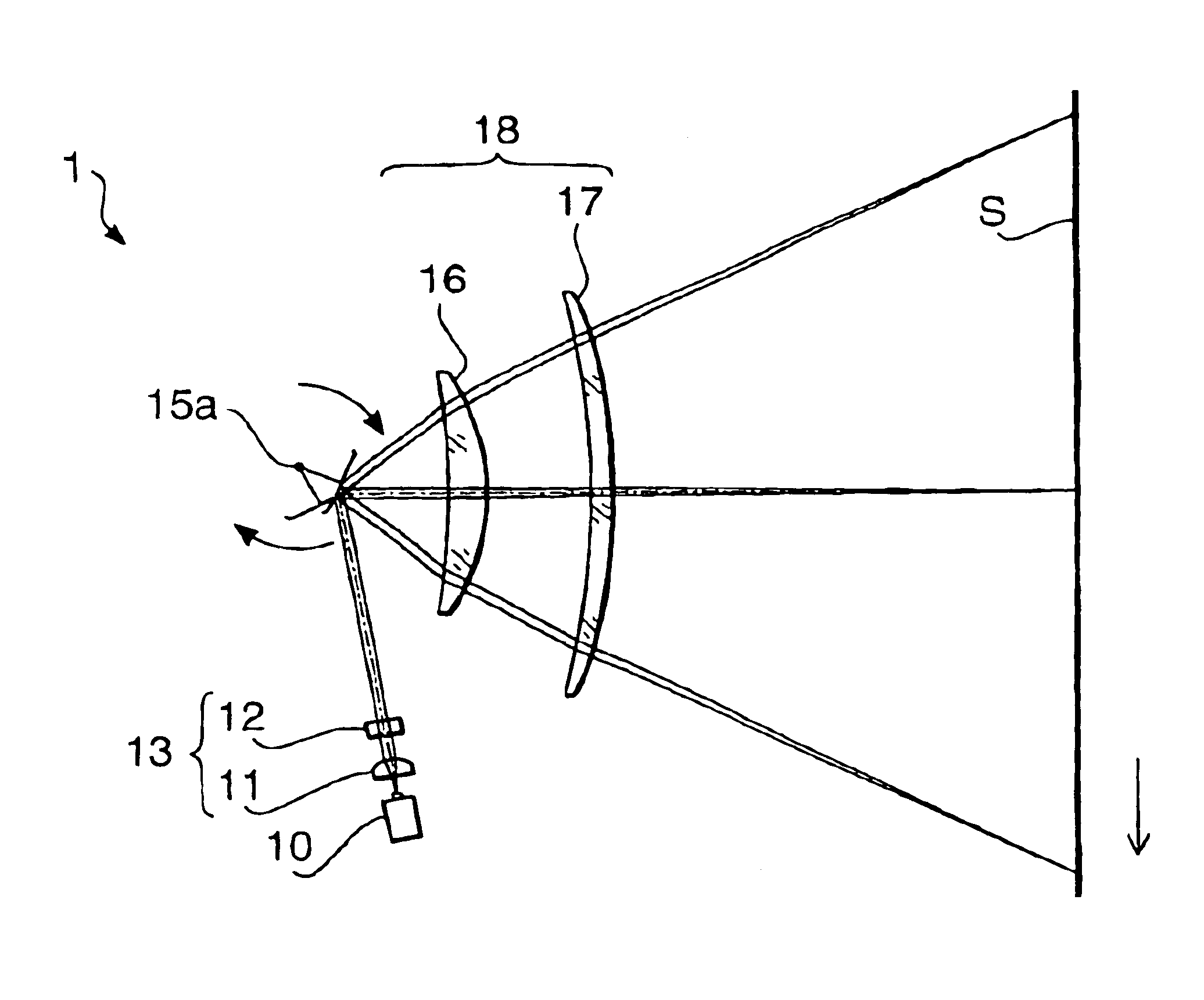
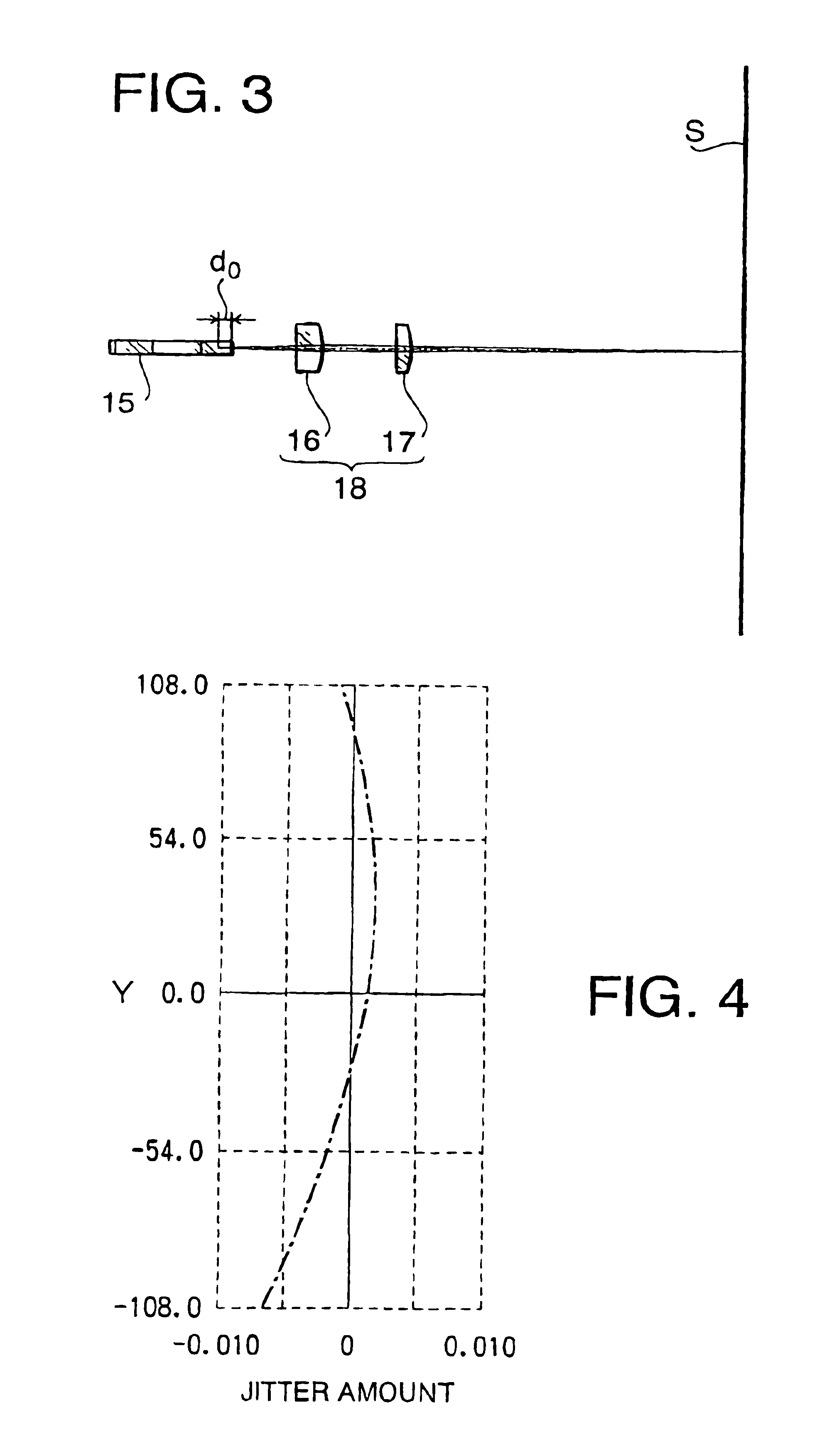
[0093]A first example according to the embodiment of the present invention will be described. A scanning optical system of the first example has a configuration similar to the scanning optical system 1 according to the embodiment of the present invention. Therefore, the first example is explained using the configuration shown in FIGS. 1-3.

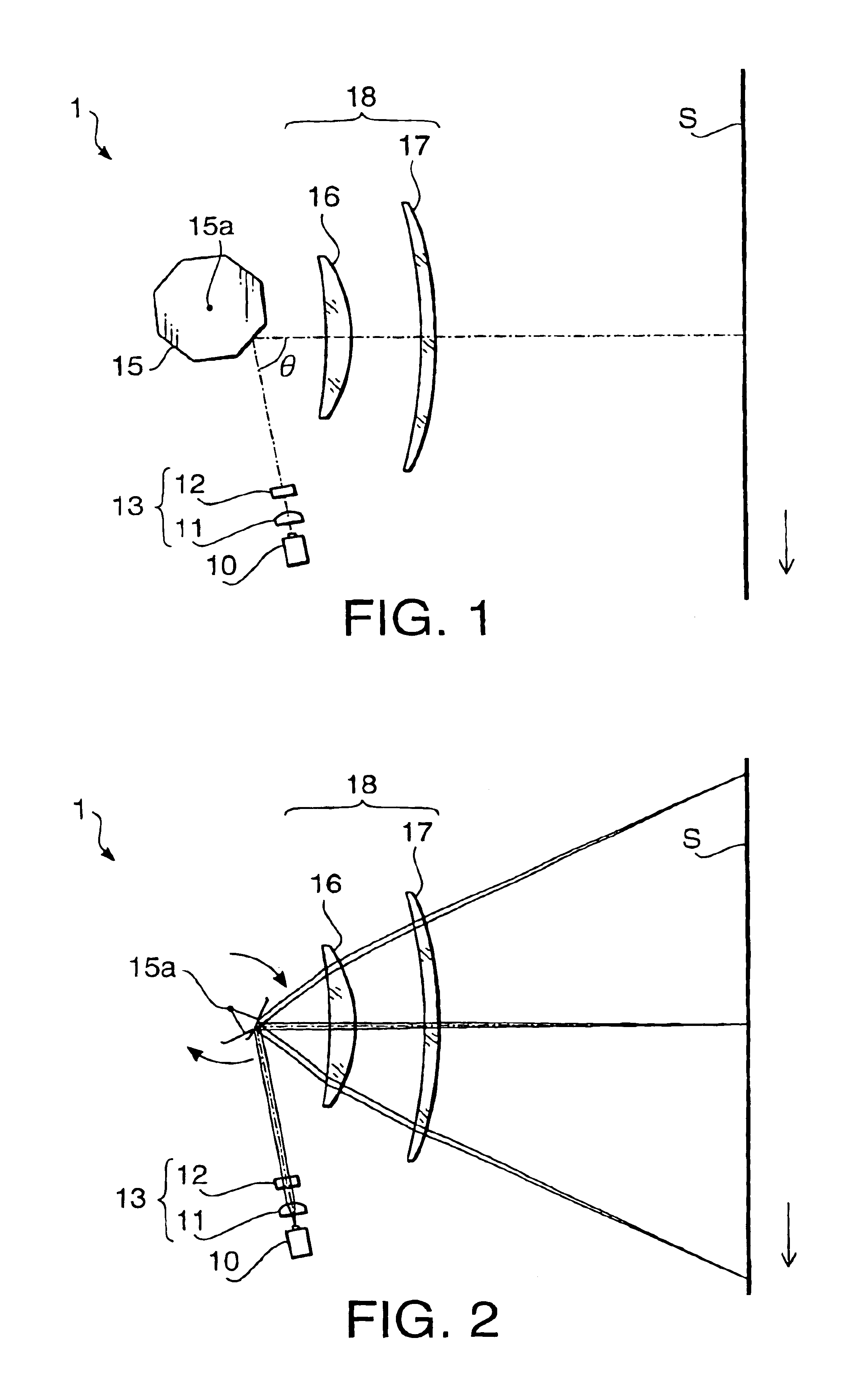
[0094]In the first example, a total focal length of the imaging optical system 18 is 150 mm. The imaging optical system 18 has the lateral magnification of −2.22 in the auxiliary scanning direction and has the half scanning width of 108 mm. The polygonal mirror 15 has the radius of the inscribed circle of 12.1 mm and has six reflective surfaces. The angle θ (see FIG. 1) formed between the beam proceeding toward the polygonal mirror 15 and the optical axis of the imaging optical system 18 in the main scanning direction is −80.0°.

[0095]When these values (m, w and f) are assigned to the condition (1), the radius of the inscribed circle of the polygona...

second example

[0106]A second example according to the embodiment of the present invention will be described. A scanning optical system of the second example has a configuration similar to the scanning optical system 1 according to the embodiment of the present invention. Therefore, the second example is explained using the configuration shown in FIGS. 1-3.

[0107]In the second example, a total focal length of the imaging optical system 18 is 150 mm. The imaging optical system 18 has the lateral magnification of −2.07 in the auxiliary scanning direction and has the half scanning width of 108 mm. The polygonal mirror 15 has the radius of the inscribed circle of 12.1 mm and has six reflective surfaces. The angle θ (see FIG. 1) formed between the beam proceeding toward the polygonal mirror 15 and the optical axis of the imaging optical system 18 in the main scanning direction is −80.0°.

[0108]When these values (m, w and f) are assigned to the condition (1) the radius of the inscribed circle of the polyg...

third example

[0119]A third example according to the embodiment of the present invention will be described. A scanning optical system of the third example has a configuration similar to the scanning optical system 1 according to the embodiment of the present invention. Therefore, the third example is explained using the configuration shown in FIGS. 1-3.

[0120]In the third example, a total focal length of the imaging optical system 18 is 140 mm. The imaging optical system 18 has the lateral magnification of −1.92 in the auxiliary scanning direction and has the half scanning width of 108 mm. The polygonal mirror 15 has the radius of the inscribed circle of 13.9 mm and has six reflective surfaces. The angle θ (see FIG. 1) formed between the beam proceeding toward the polygonal mirror 15 and the optical axis of the imaging optical system 18 in the main scanning direction is −80.0°.

[0121]When these values (m, w and f) are assigned to the condition (1), the radius of the inscribed circle of the polygona...


PUM


Abstract

There is provided a scanning optical system which includes a light source, a line-like image forming optical system, a polygonal mirror, and an imaging optical system. The line-like image forming optical system forms a line-like image extending in the main scanning direction in the vicinity of a reflective surface of the polygonal mirror, and if the number of reflective surfaces of the polygonal mirror is less than or equal to six and if |m|>1.85, the following condition (1) is satisfied:r<5 cos(w / 2f) / [2|m|{1− cos(w / 2f)}]  (1)where r represents a radius of an inscribed circle of the polygonal mirror, m represents a lateral magnification of the imaging optical system in the auxiliary scanning direction, f represents a focal length of the imaging optical system in the main scanning direction, and w represents half of a scanning width.

Description

BACKGROUND OF THE INVENTION[0001]The present invention relates to a scanning optical system for forming a laser beam scanning on a scan target surface.[0002]In general, a scanning optical system is employed in, for example, a laser beam printer, a digital copying machine, a laser fax machine and a laser plotter. In such an apparatus, the scanning optical system is used to form a beam spot which is on / off modulated according to image information and which scans on the scan target surface (e.g., a photoconductive drum).[0003]Hereafter, a direction in which a beam spot is scanned on the scan target surface is referred to as a main scanning direction, and a direction perpendicular to the main scanning direction on the scan target surface is referred to as an auxiliary scanning direction. In the following description, the shape of optical elements, directions of power of the optical elements and the like are described with reference to the main and auxiliary scanning directions on the sc...

Claims


Application Information

Patent Timeline
IPC IPC(8): B41J2/44G02B26/08G02B26/10H01J3/00H01J5/02H01J5/16H01J3/14H04N1/113G02B26/12
CPCG02B26/124G02B26/125
Inventor TAKAKUBO, YUTAKA
Owner ASAHI KOGAKU KOGYO KK
Why Eureka
Try Eureka