
Ultra wideband networks system and method capable of switching to high-speed mode or low-speed mode

a network system and wideband technology, applied in the direction of connection management, angle demodulation by phase difference detection, electrical equipment, etc., can solve the problems of serious interference, low compatibility, and the inability to adapt to a low-power sensor network system mainly using location recognition technology, so as to reduce the noise factor of the uwb network receiver

Inactive Publication Date: 2007-04-12
SAMSUNG ELECTRONICS CO LTD
View PDF10 Cites 11 Cited by
  • Summary
  • Abstract
  • Description
  • Claims
  • Application Information

AI Technical Summary

Benefits of technology

[0029] The UWB receiver may further comprise an analog matched filter which integrates, samples, and holds an amplified signal; and an amplifier which amplifies the input signal and outputs an amplified signal to the analog matched filter and the AGC; wherein the PLL transmits a symbol rate clock to the analog matched filter to control the phase of the filtered signal.
[0030] The UWB network receiver may further comprise a band pass filter (BPF) which filters a reception signal, and passes a signal of a frequency band of the MB-OFDM type or a frequency band of the DS-CDMA type; a low noise amplifier (LNA) which amplifies the signal from the BPF and lowers a noise factor of the UWB network receiver; a voltage controlled oscillator (VCO) which generates an oscillation signal according to a control voltage from the PLL; a mixer which mixes the amplified signal and the oscillation signal; a low pass filter (LPF) which blocks a high frequency noise component of the mixed signal and passes a signal of a low frequency band to the AGC; and a multi-tone generator which generates the oscillation signal as a local oscillation signal of an I channel and a Q channel and transmits the oscillation signal to the mixer.
[0031] When there is no data received, the mode switch may be switched to the DS-CDMA modem so that the UWB network transmitter is in the low-speed operation mode.
[0032] There is also provided a method of switching transmission modes in an ultra wide band network transmitter, the method comprising: receiving a command to transmit data; and switching to a multi-band orthogonal frequency division multiplexing (MB-OFDM) modem to select a to the high-speed operation mode.
[0033] The method may further comprise transmitting the data in the high-speed operation mode.
[0034] After the data is transmitted, whether to remain in the high-speed operation mode may be determined, and when a low-speed operation mode is desired, switching to the direct sequence code division multiple access (DS-CDMA) modem to select the low-speed operation mode.

Problems solved by technology

However, even though many companies adopt the MB OFDM type method for high-speed communication, this method is not appropriate for a low-power sensor network system mainly using a location recognition technology.
In addition, because the MB-OFDM technology is not compatible with other sensor network systems, an extra transceiver is needed to subscribe to the sensor network systems.
However, the high-speed mode of the DS-CDMA is not adopted by many companies so that compatibility is low.
Additionally, when a transceiver of the MB-OFDM type and a transceiver of the DS-CDMA type are used at the same time, because the communication types are different, each transceiver interprets the other transceiver's frequencies as noise so that serious interference occurs.

Method used


Image

  • Ultra wideband networks system and method capable of switching to high-speed mode or low-speed mode
  • Ultra wideband networks system and method capable of switching to high-speed mode or low-speed mode
  • Ultra wideband networks system and method capable of switching to high-speed mode or low-speed mode

Examples


Embodiment Construction

[0043] Hereinafter, an exemplary embodiment of the present invention will be described in detail with reference to the accompanying drawing figures.

[0044] In the following description, same drawing reference numerals are used for the same elements even in different drawings. The matters defined in the description such as a detailed construction and elements are nothing but the ones provided to assist in a comprehensive understanding of the invention. Thus, it is apparent that the present invention can be carried out without those defined matters. Also, well-known functions or constructions are not described in detail since they would obscure the invention in unnecessary detail.

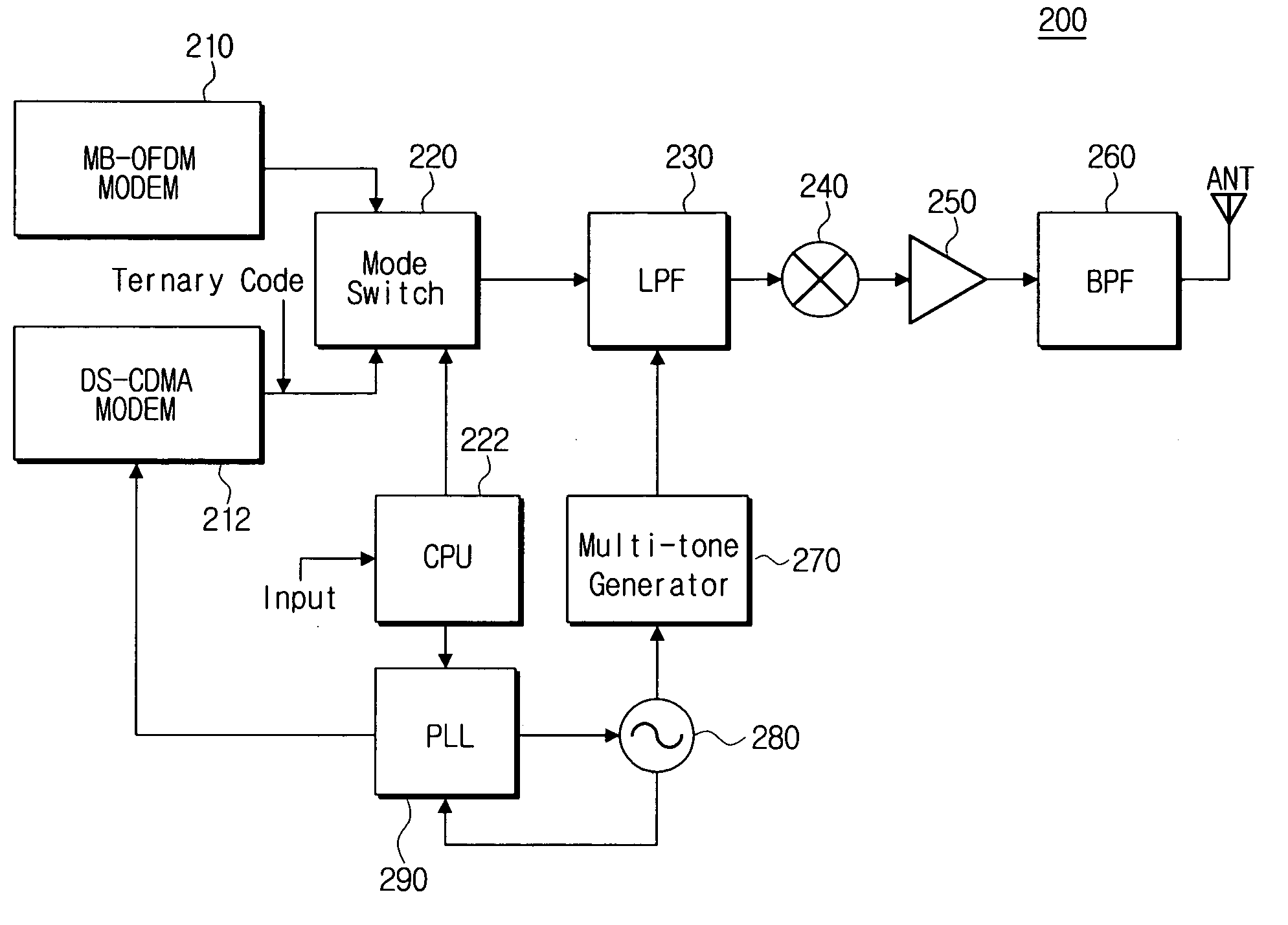
[0045]FIG. 2 is a schematic diagram showing the construction of a UWB network transmitter according to an exemplary embodiment of the present invention.

[0046] The UWB network transmitter 200 according to an exemplary embodiment of the present invention includes an MB-OFDM modem 210, a DS-CDMA modem 212, a m...


PUM


Abstract

An ultra wideband network transmitter and receiver, and a method capable of switching to a high-speed mode or a low-speed mode are provided. The transmitter includes a multi-band orthogonal frequency division multiplexing (MB-OFDM) modem; a direct sequence code division multiple access (DS-CDMA) modem; a mode switch which switches to the MB-OFDM modem or the DS-CDMA modem according to a mode control signal; a phase lock loop (PLL) which locks a frequency used for MB-OFDM type modulation or the DS-CDMA type modulation; and a central processing unit (CPU) controls the PLL and mode switch. The receiver includes an MB-OFDM modem; an DS-CDMA modem; an automatic gain controller; an analog-to-digital converter; an PLL; a mode switch; and an CPU. The method includes receiving a command to transmit data; and switching to an MB-OFDM modem to select to a high-speed operation mode.

Description

CROSS-REFERENCE TO RELATED APPLICATION [0001] This application claims priority from Korean Patent Application No. 10-2005-0090698, filed Sep. 28, 2005 in the Korean Intellectual Property Office, the entire contents of which are incorporated herein by reference. BACKGROUND OF THE INVENTION [0002] 1. Field of the Invention [0003] Apparatuses, systems, and methods consistent with the present invention relate to an ultra wideband network communications, and more particularly, to switching to a high-speed mode or a low-speed mode, in order for an ultra wideband communication terminal device such as a home network device to selectively perform high-speed communications or low-speed communications. [0004] 2. Description of the Related Art [0005] In general, ultra wideband (UWB) is a wireless transmission technology whose a frequency bandwidth is 20 percent or 500 MHz more than a central frequency bandwidth. Accordingly, bandwidth gets broader in the frequency band and conversely, the trans...

Claims


Application Information

Patent Timeline
Patent Type & Authority Applications(United States)
IPC IPC(8): H03D3/24H04B1/707H04W76/02H04B1/7075H04B1/7093H04B1/713H04J11/00H04W48/18
CPCH04B1/71635H04B1/71637H04B1/7183H04B1/50H04B1/04H04B1/48
Inventor KIM, WAN-JINKOO, JAE-HYUN
Owner SAMSUNG ELECTRONICS CO LTD
Learn More