
Evaporative cooling system for fuel cell systems using cathode product water

Inactive Publication Date: 2007-04-12
GM GLOBAL TECH OPERATIONS LLC
View PDF6 Cites 16 Cited by
  • Summary
  • Abstract
  • Description
  • Claims
  • Application Information

AI Technical Summary

Benefits of technology

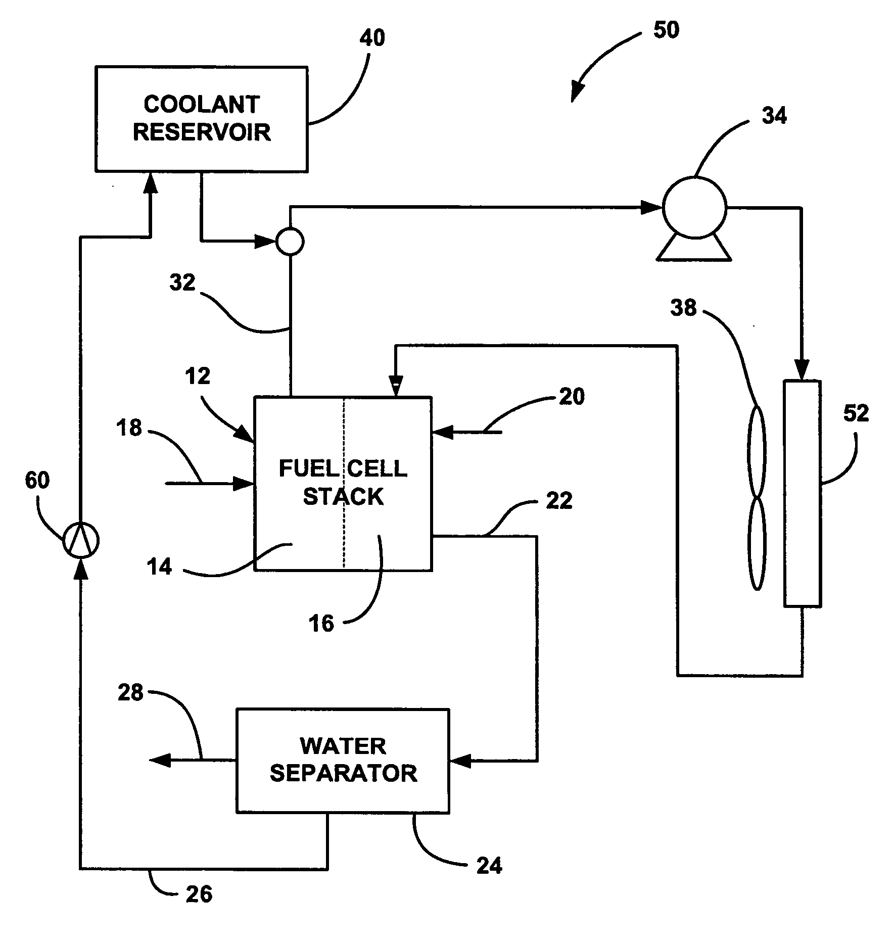
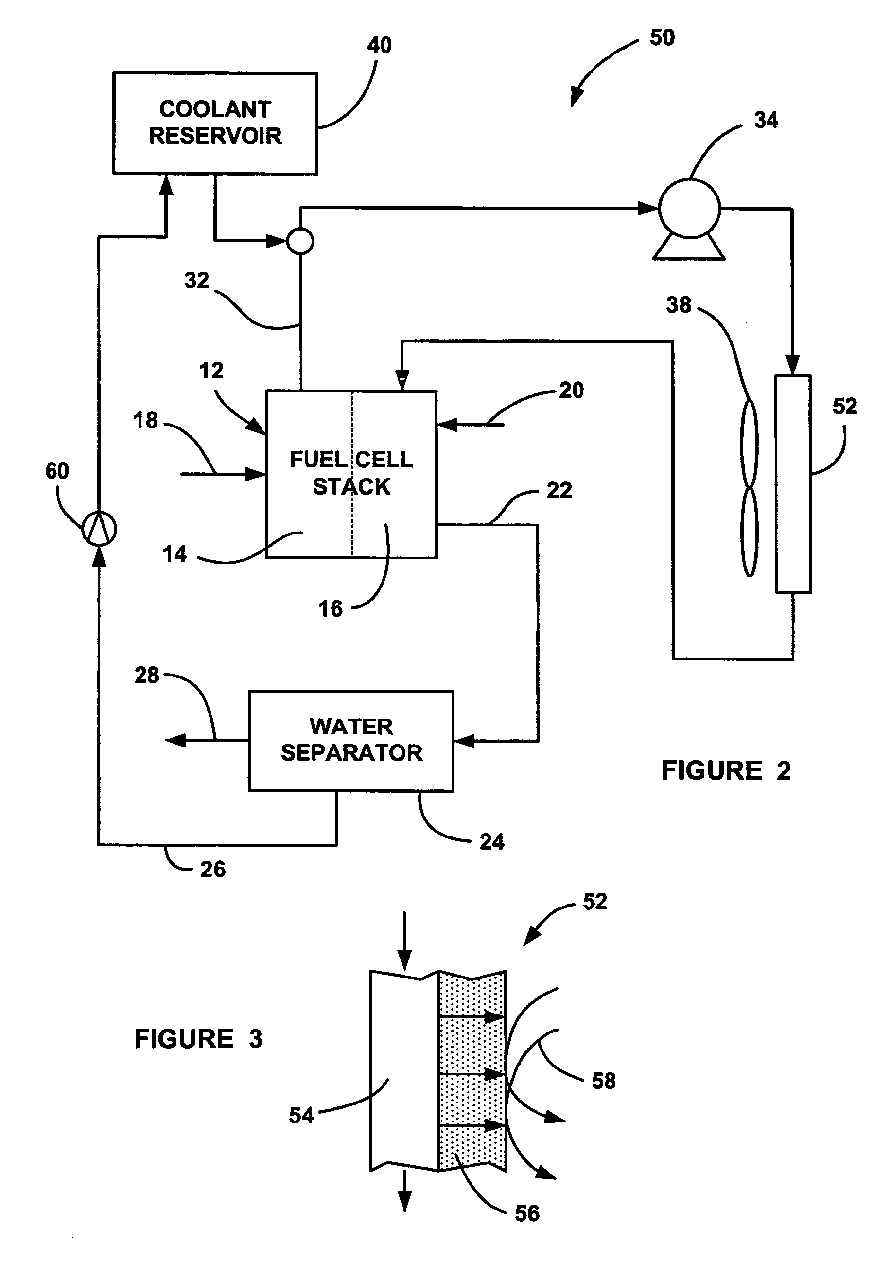
[0012] In accordance with the teachings of the present invention, a fuel cell system including a fuel cell stack is disclosed that employs a thermal sub-system having a specialized radiator. A water based or water containing cooling fluid flowing through the fuel cell stack is directed through the radiator to remove or dissipate waste heat before the cooling fluid is returned to the stack. Part of the heat dissipation is provided by radia

Problems solved by technology

Excessive stack temperatures above the optimum temperature may damage fuel cell components, reducing the lifetime of the fuel cells.
Also, stack temperatures below the optimum temperature reduces the stack performance.
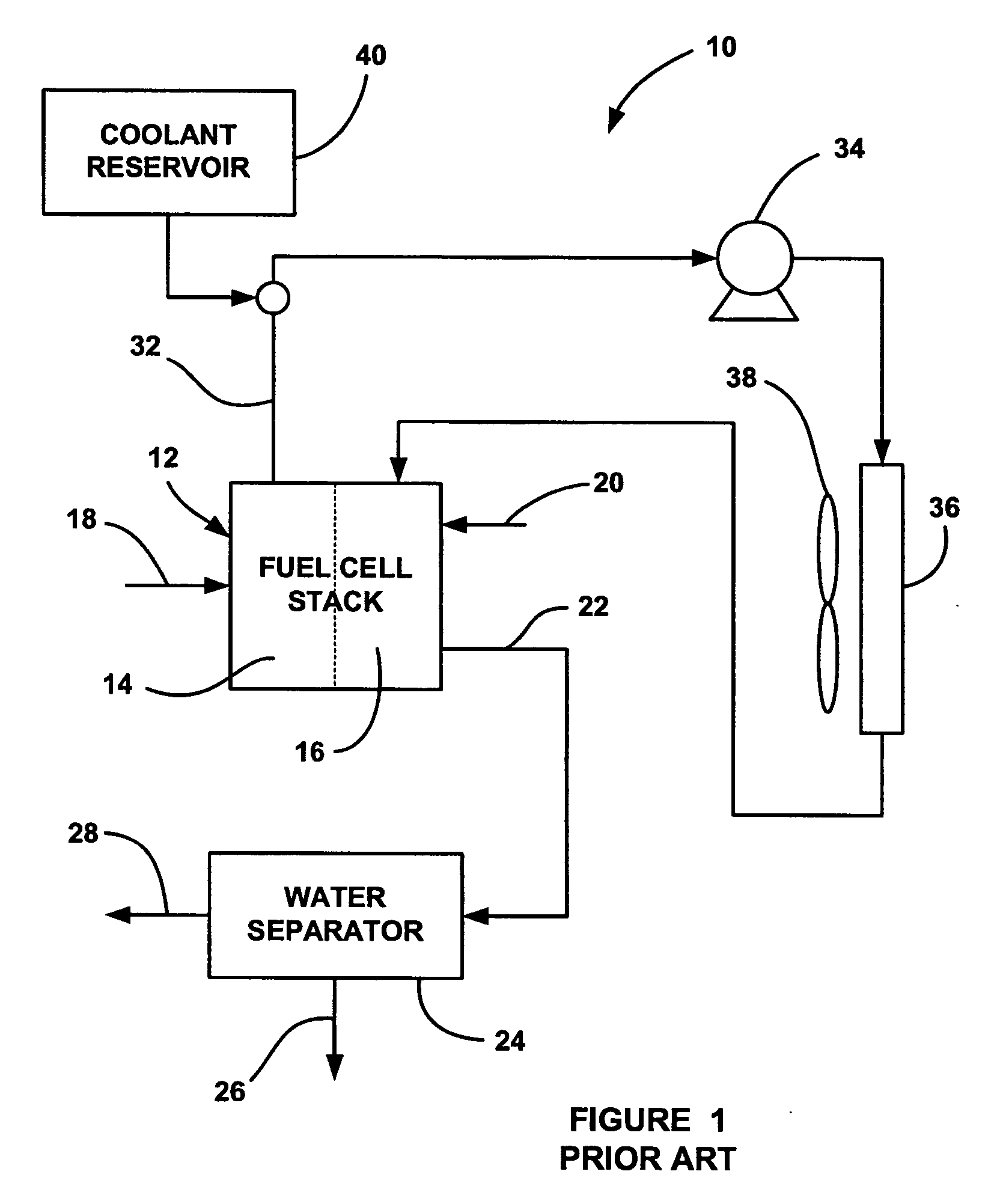
Because liquid water may be exhausted to the environment from the system 10, a potential drawback occurs because the discharged water may form ice on the road, and may provide other inconveniences.

Method used


Image

  • Evaporative cooling system for fuel cell systems using cathode product water
  • Evaporative cooling system for fuel cell systems using cathode product water
  • Evaporative cooling system for fuel cell systems using cathode product water

Examples


Embodiment Construction

[0017] The following discussion of the embodiments of the invention directed to a thermal sub-system for a fuel cell system is merely exemplary in nature, and is in no way intended to limit the invention or its application in uses.

[0018]FIG. 2 is a plan view of a fuel cell system 50, according to an embodiment of the present invention, similar to the fuel cell system 10, where like elements are identified with the same reference numeral. In the system 50, the radiator 36 is replaced with a radiator 52. A cross-sectional view of a portion of the radiator 52 is shown in FIG. 3. The radiator 52 includes cooling fluid flow channels 54 and a selectively permeable wall portion 56. As discussed above, the radiator 52 receives a heated cooling fluid from the stack 12. In one non-limiting embodiment, the cooling fluid is a mixture of ethylene glycol and water of varying concentrations. However, other water based cooling fluids may be applicable to provide the desired cooling. With increasin...


PUM

PropertyMeasurementUnit
Temperatureaaaaaaaaaa
Pressureaaaaaaaaaa
Concentrationaaaaaaaaaa

Abstract

A fuel cell system including a fuel cell stack that employs a thermal sub-system having a specialized radiator. The cooling fluid from the fuel cell stack is directed through the radiator to remove or dissipate waste heat before the cooling fluid is returned to the stack. The radiator includes a selectively permeable wall that allows liquid water or water vapor to selectively permeate therethrough to the outside of the radiator, where it is evaporated to increase the cooling ability of the radiator. A water separator separates water from the cathode exhaust of the fuel cell stack, which is used to replenish water in the cooling fluid that is evaporated through the radiator wall.

Description

BACKGROUND OF THE INVENTION [0001] 1. Field of the Invention [0002] This invention relates generally to a thermal sub-system for a fuel cell system and, more particularly, to a thermal sub-system for a fuel cell system that employs a radiator having a selectively permeable wall to allow water in a cooling fluid flowing through the radiator to permeate through the wall and be evaporated to increase the cooling ability of the radiator, where the water separated from the cathode exhaust is used to replenish the evaporated cooling fluid water. [0003] 2. Discussion of the Related Art [0004] Hydrogen is a very attractive fuel because it is clean and can be used to efficiently produce electricity in a fuel cell. A hydrogen fuel cell is an electrochemical device that includes an anode and a cathode with an electrolyte therebetween. The anode receives hydrogen gas and the cathode receives oxygen or air. The hydrogen gas is dissociated in the anode to generate free protons and electrons. The ...

Claims


Application Information

Patent Timeline
IPC IPC(8): H01M8/04
CPCB01D53/228B01D61/362B01D69/10B01D71/08H01M8/04059H01M8/04156H01M8/04253H01M2250/20Y02E60/50Y02T90/32Y02T90/40B01D69/108
Inventor DRUENERT, VOLKER
Owner GM GLOBAL TECH OPERATIONS LLC
Learn More