Inshot burner flame retainer

a technology of burner and flame retainer, which is applied in the direction of burners, combustion types, combustion processes, etc., can solve the problems of inability to ignite, noise and nitrogen oxide formation, and inability to ignite,

Inactive Publication Date: 2007-04-12
CARRIER CORP
View PDF7 Cites 22 Cited by
  • Summary
  • Abstract
  • Description
  • Claims
  • Application Information

AI Technical Summary

Benefits of technology

[0008] According to another embodiment of the invention, the passages are formed such that in radial cross section, they are annular in form and are circumferentially equally spaced around a central opening. The restricted radial width prevents flashback, while the circumferential length is sufficient to prevent sooting.

Problems solved by technology

Some of the problems associated with conventional inshot burner designs are improper ignition, flame instability, noise and nitrogen oxides formation.
Ignition problems can arise when the ignition location is critical.
Flame liftoff is a major cause of the noise associated with the operation of inshot burner nozzles.
This condition can cause overheating and deterioration of the nozzle.
While such designs are helpful in addressing the problems discussed hereinabove, they do not adequately address the problem of flashback and the propensity for producing soot, particularly when using propane rather than natural gas as the fuel.
However, when dealing with other design limitations on the overall size of the burner, simply downsizing the perimeter passages results in insufficient primary air for combustion.
That is, as the size of the passages is reduced to prevent flashback, there is a tendency to cause a yellowing of the flame tip which, in turn, tends to cause the formation of soot.

Method used


Image

  • Inshot burner flame retainer
  • Inshot burner flame retainer
  • Inshot burner flame retainer

Examples


Embodiment Construction

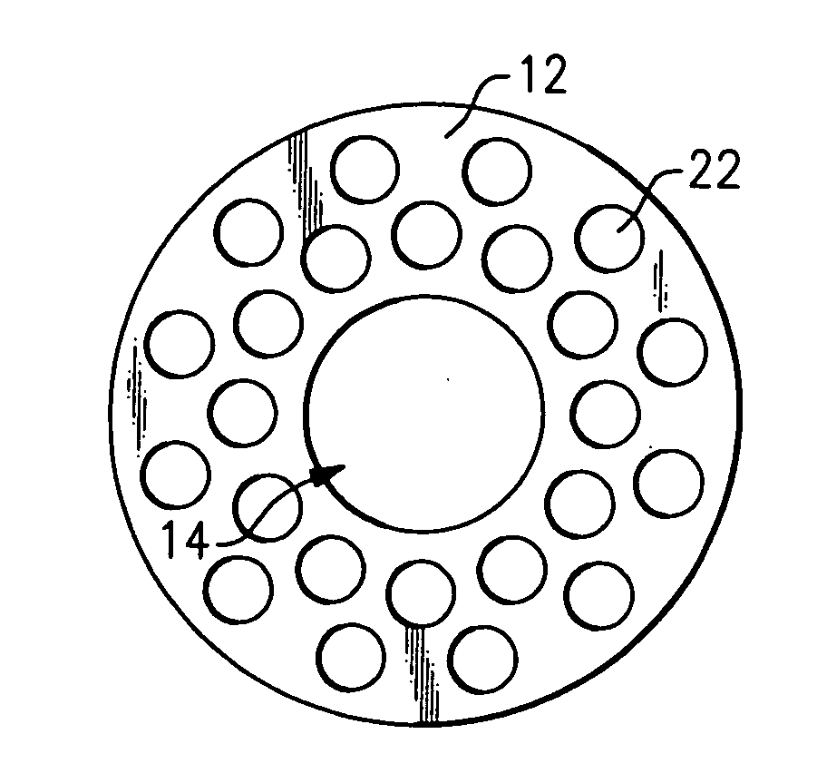
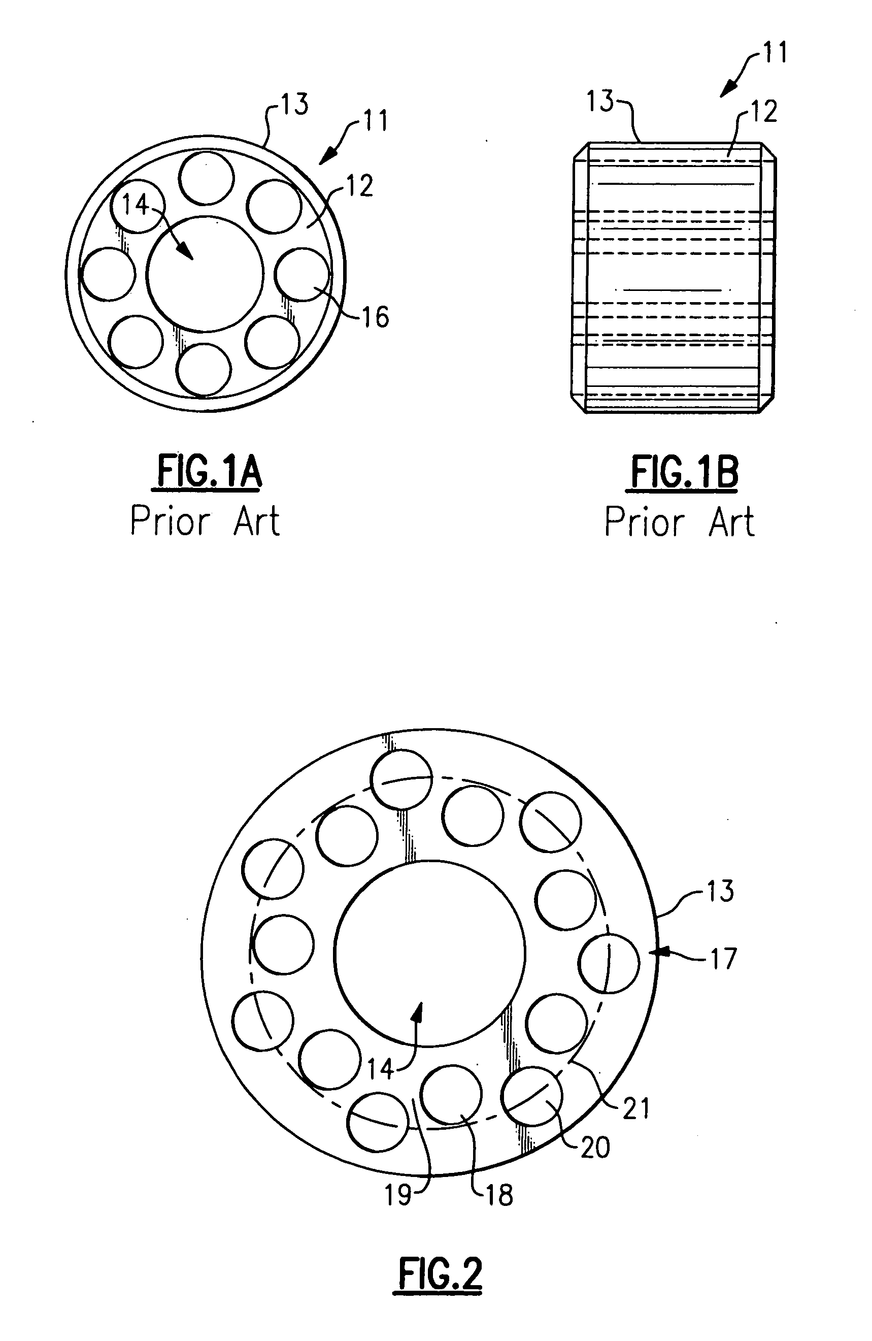
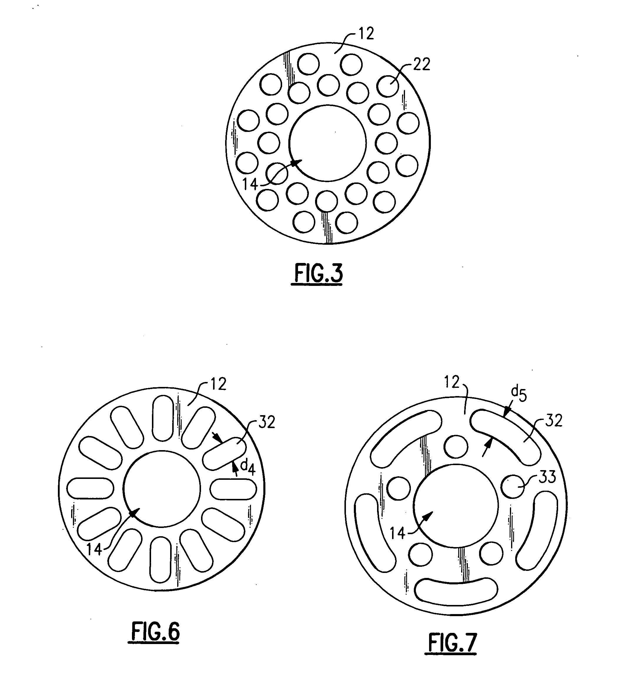
[0018] Referring now to FIGS. 1A and 1B, there is shown a flame retainer structure in accordance with the prior art. The flamer retainer, shown generally at 11 comprises a cylinder 12 having an outer surface 13 and a central passage 14 extending therethrough. A plurality of secondary openings 16 of smaller diameter are arranged circularly around the central passage 14.

[0019] While the size of the central passageway 14 is somewhat decided by other considerations, the designers have taken some liberty with the size of the secondary openings 16 to bring about desired results. Generally, the size of the secondary openings 16 has been chosen to bring about the desired performance characteristics. While the number and particular location of the secondary openings has been varied to bring about particular results, the secondary openings have generally been circular in form with their axes aligned with the axes of the central passage 14.

[0020] The applicants have found that the use of pro...


PUM


Abstract

A flame retainer for an inshot burner has a plurality of secondary openings that take full advantage of the space available to limit their size in one dimension to prevent flashbacks but are sufficient in size to allow for the flow of sufficient primary air so as to prevent yellow tipping and soot formation. The slots are elongated in radially cross-sectional shape, and their widths are limited to a dimension of 0.13 inches. The width is also limited to dimensions equal to or greater than 0.09 inches so as to prevent the formation of soot.

Description

TECHNICAL FIELD [0001] This invention relates generally to residential furnaces and, more particularly, to inshot burners with flame retainers. BACKGROUND OF THE INVENTION [0002] Gas fired appliances, such as residential and light commercial heating furnaces, often use a particular type of gas burner commonly referred to as an inshot burner. In this type of burner, fuel gas under pressure passes through a central port disposed at the inlet of a venturi burner nozzle. Atmospheric air is drawn into the burner nozzle and mixes with the fuel gas as it passes through the burner nozzle. In some constructions, a burner head insert, also referred to as a flame retention insert, made of compressed sintered or powdered metal is mounted in the outlet end of the tube. In operation, as gas is injected into the inlet end of the nozzle, it entrains air into the nozzle. This primary air / gas mix flows through the nozzle to the burner head insert. The primary air / gas mix passes through outlet opening...

Claims


Application Information

Patent Timeline
Patent Type & Authority Applications(United States)
IPC IPC(8): F23D14/62
CPCF23D14/583
Inventor ZIA, NINEV KARLGARLOCH, DUANE D.
Owner CARRIER CORP
Why Eureka
Try Eureka