
Wireless device and method for radio control

a wireless communication and radio control technology, applied in the field of wireless communication devices and radio control methods, can solve the problems of frequency mixing, interference of one radio to another, interference of in-band or out-band frequencies, etc., and achieve the effect of reducing channel interference and reducing interferen

Inactive Publication Date: 2007-04-12
ACCTON TECHNOLOGY CORPORATION
View PDF5 Cites 29 Cited by
  • Summary
  • Abstract
  • Description
  • Claims
  • Application Information

AI Technical Summary

Benefits of technology

The invention provides a way to isolate two radios that operate in different channels, reducing interference between them. This is done by using a cognitive radio to scan the wireless area and gather information about the operational status of a free radio. The cognitive radio then analyzes this information and configures its own future operation to minimize interference with the free radio. This results in a more reliable and efficient wireless network.

Problems solved by technology

However, the inherent problem with a co-located two-radio system is the interference of one radio to another.
There are several causes for interferences of in-band or out-band frequencies.
One can be attributed to sidelobe interferences.
That is, the sidelobes of one channel, fall in the in-band adjacent or alternative channels and interfere with another carriers operating therein.
Another cause of interference is due to third order intermodulation, in which the fundamental frequency of a signal and the second harmonic of aother signal result in frequency mixing.
A third cause of interference arises from the interference of the second harmonic of a signal in a band with other signals out of the band.
The non-adaptive method in common guard and attenuation solely provides the purpose of screening, and is yet to provide a satisfactory result towards reducing interferences.
However, the conventional method poses limitation towards the allowed spacing between two operating channels and between two antennae, thereby reducing flexibility.

Method used


Image

  • Wireless device and method for radio control
  • Wireless device and method for radio control
  • Wireless device and method for radio control

Examples


Embodiment Construction

[0019] The disclosed embodiments provide an approach of cognitive radio techniques to detect network conditions and adapt to them, thereby reducing interference with other co-located radios.

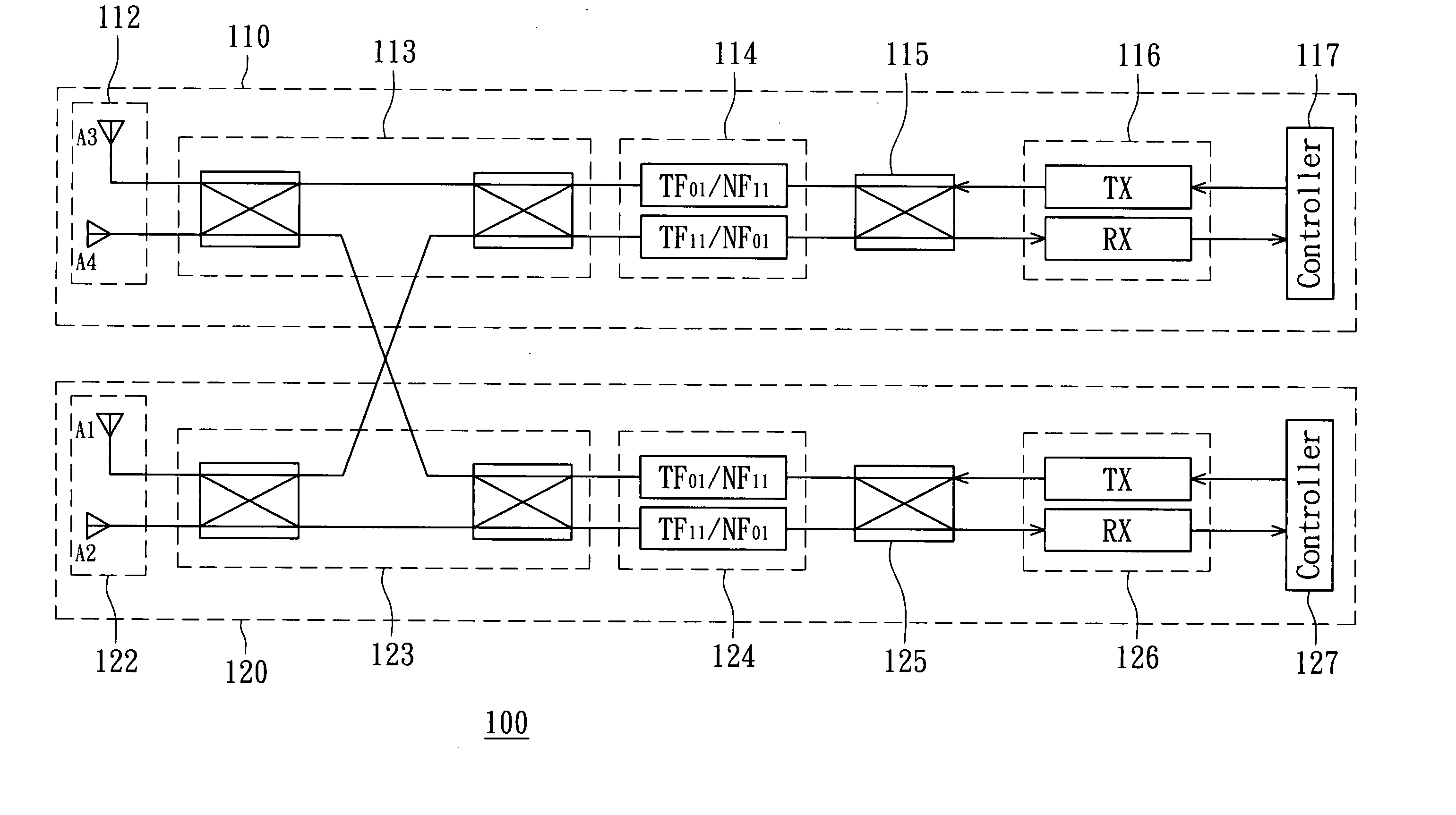
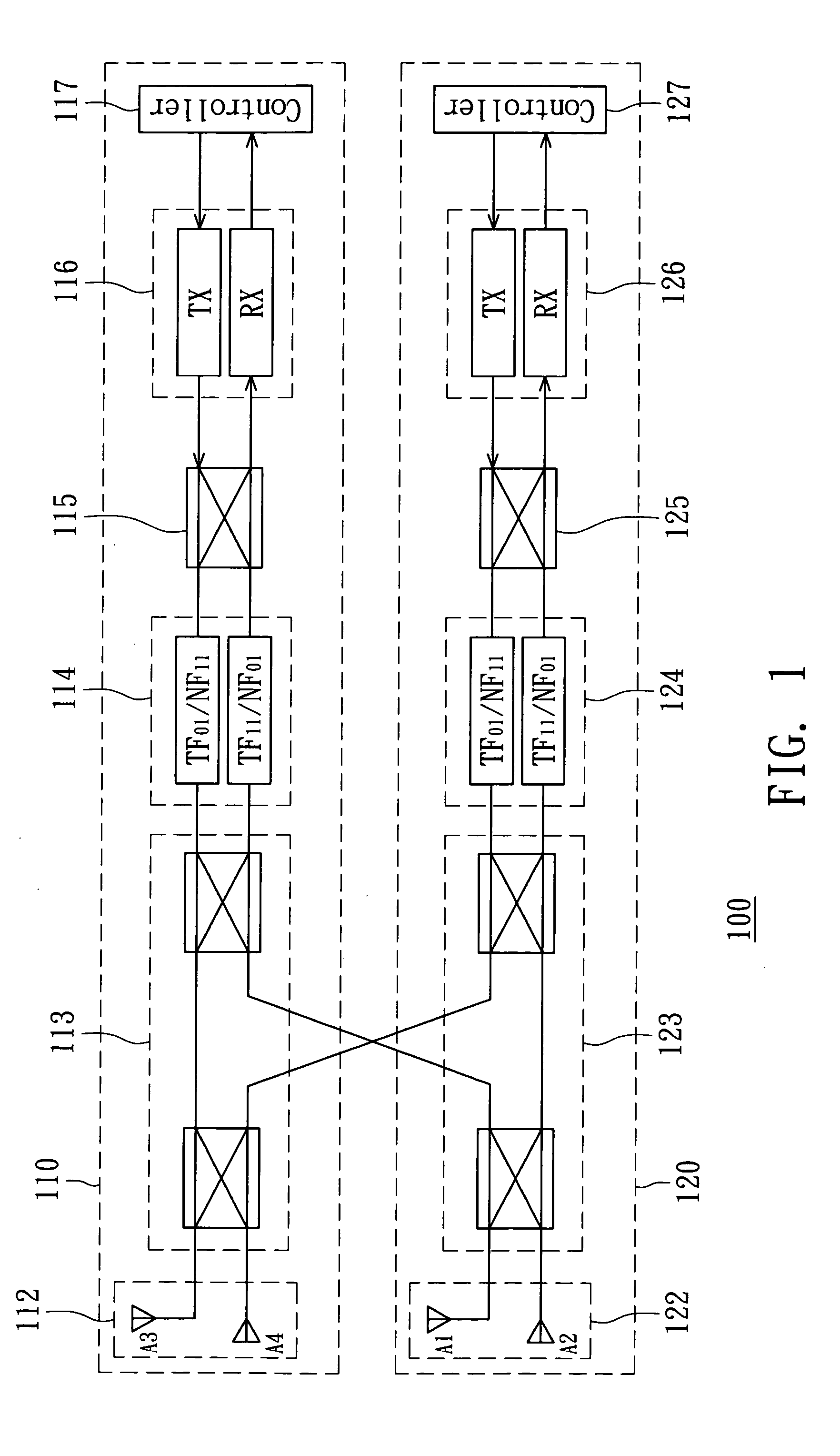
[0020]FIG. 1 shows a block diagram of a wireless device according to an embodiment of the invention. The wireless device 100 includes a cognitive radio 110 and a free radio 120. The free radio 120 includes an antenna assembly 122, a first switch network 123, a filter element 124, a second switch network 125, a radio circuit 126, and a controller 127. The wireless device 100 is connected to a network (not shown). The antenna assembly 122is for receiving signals from the wireless area that are to be sent to the radio circuit 126, or transmitting signals received from the radio circuit 126 to the wireless area. The controller 127 processes data to and from the network. In some embodiments, the controller 127 includes a baseband processor (BBP) and a media access control (MAC) (not shown). The radio...


PUM


Abstract

A method of radio control, adapted in a wireless device that includes a cognitive radio and a free radio. First, the cognitive radio scans within vicinity or range to receive frames sent from or to the free radio, for retrieving therefrom network information of on-air frames indicative of past operational status of the free radio. Next, network operation commands of the free radio are sensed by the cognitive radio, in which the network operations commands being indicative of present operational status of the free radio. Then, a step is performed using the cognitive radio to read network flags generated in the free radio indicative of future operational status of the free radio. Following operation of the cognitive radio is then configured based on at least one of the past, present and future operational status of the free radio so as to reduce channel interferences with the free radio

Description

BACKGROUND OF THE INVENTION [0001] 1. Field of the Invention [0002] The invention relates in general to a communications device, and more particularly to a wireless communications device and a method of radio control adapted therefor. [0003] 2. Description of the Related Art [0004] In a network device, two radios are increasingly preferred over one radio in order to improve quality of link and service, and to expand functionality in networking. For instance, user can have two radios be used as access points to enhance throughput and latency; or have one radio be used as an access point and have another be dedicated to operate as monitor for site surveying or operate as bridge or wireless distribution service for backhauling. However, the inherent problem with a co-located two-radio system is the interference of one radio to another. [0005] There are several causes for interferences of in-band or out-band frequencies. One can be attributed to sidelobe interferences. That is, the side...

Claims


Application Information

Patent Timeline
Patent Type & Authority Applications(United States)
IPC IPC(8): H04B1/18H04W48/16H04W88/06
CPCH04W48/16H04W88/06
Inventor LIU, I-RU
Owner ACCTON TECHNOLOGY CORPORATION
Learn More