Tissue augmentation, stabilization and regeneration Technique

a tissue augmentation and stabilization technology, applied in the field of tissue augmentation, stabilization and regeneration techniques, can solve the problems of high pressure spikes, largely restricted effort, and inability to promote bone regeneration, and achieve the effect of stabilizing the fracture site and promoting the growth of new bon

a tissue augmentation and stabilization technology, applied in the field of tissue augmentation, stabilization and regeneration techniques, can solve the problems of high pressure spikes, largely restricted effort, and inability to promote bone regeneration, and achieve the effect of stabilizing the fracture site and promoting the growth of new bon

US20070083205A1Inactive Publication Date: 2007-04-12DEPUY SPINE INC (US)

Image

  • Tissue augmentation, stabilization and regeneration Technique
  • Tissue augmentation, stabilization and regeneration Technique
  • Tissue augmentation, stabilization and regeneration Technique

Examples


Embodiment Construction

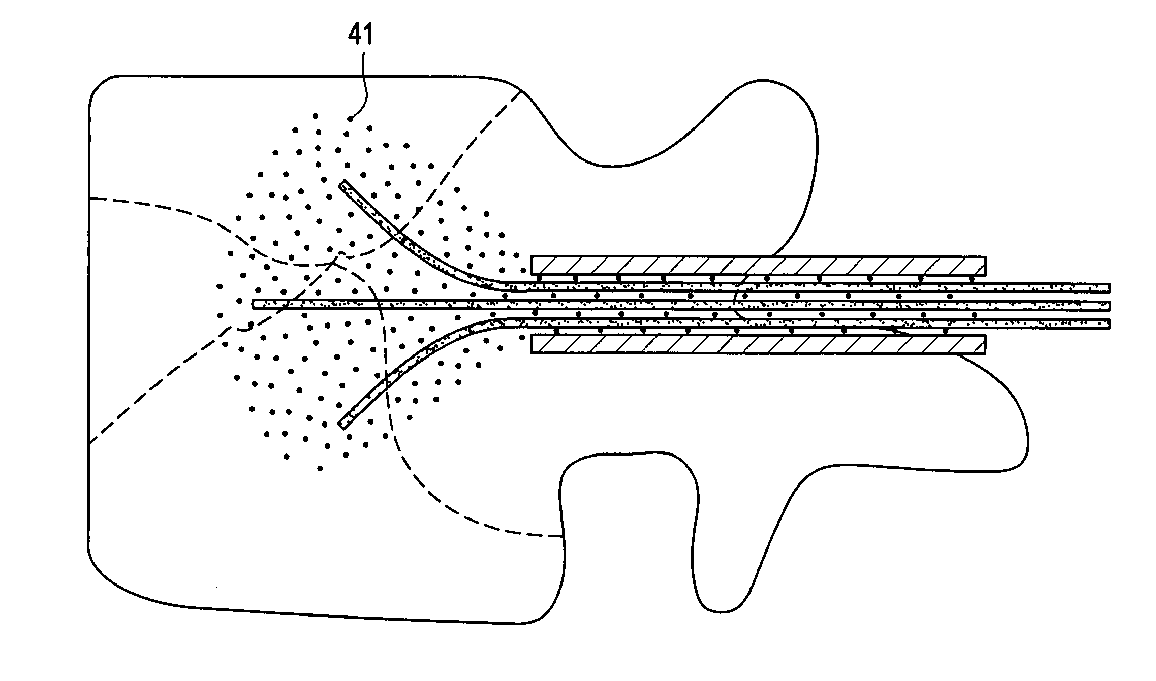
[0022] In one preferred embodiment, and now referring to FIG. 2, the method of the present invention treats an osteoporotic vertebral body compression fracture.

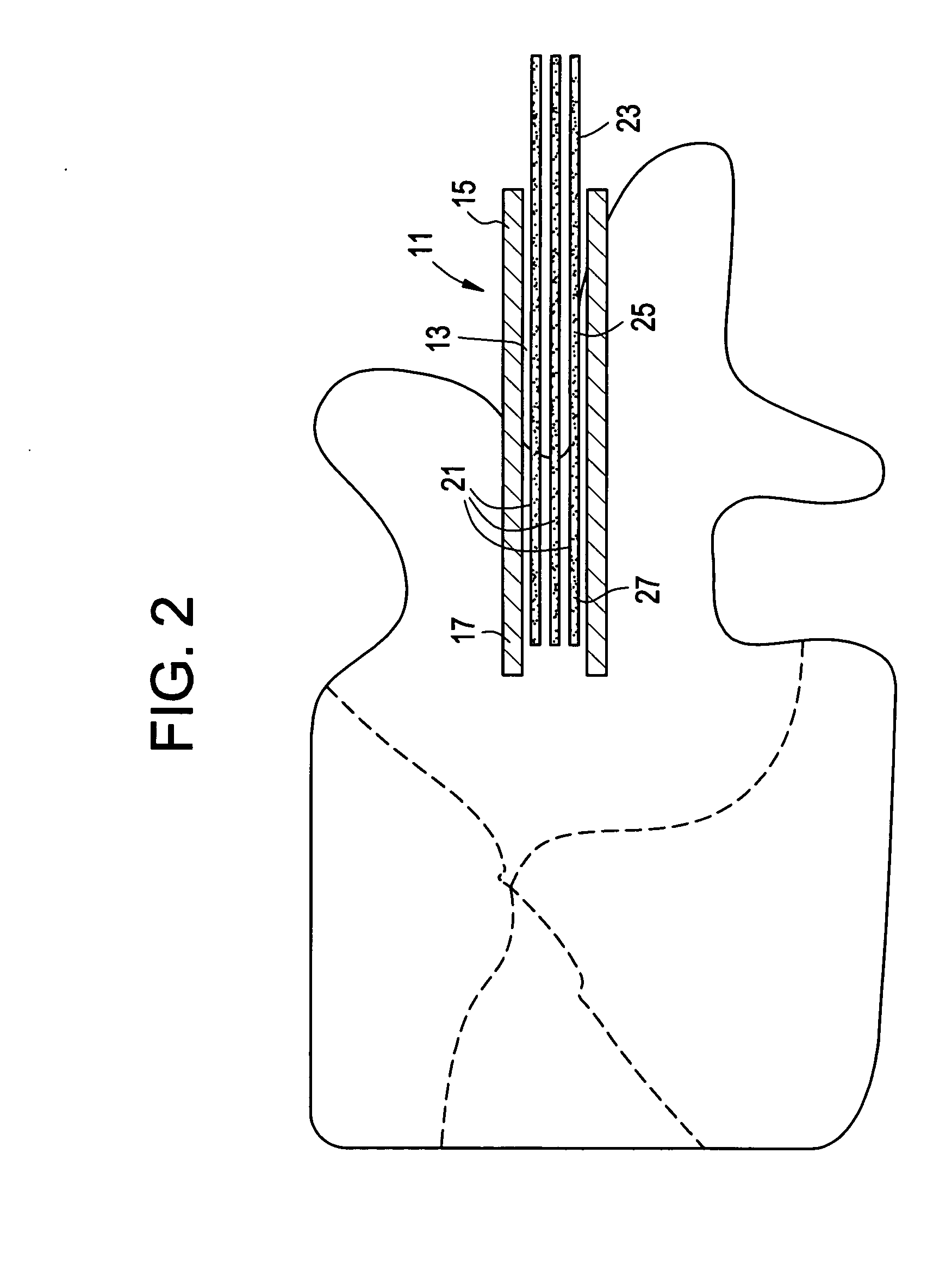
[0023] First, and now referring to FIG. 2, the device 1 of the present invention is provided. The device comprises: [0024] a) a trocar 11 having a longitudinal throughbore 13, a proximal end 15 and a distal end 17, and [0025] b) a plurality of flexible reinforcement rods 21 having a proximal end portion 23, an intermediate portion 25, and a distal end portion 27,

[0026] The trocar containing the rods is inserted into the fractured cortical shell and fractured cancellous bone regions of the vertebral body.

[0027] Next, and now referring to FIG. 3, the plurality of flexible reinforcement rods are advanced distally into the vertebral body from within the bore of the trocar. Upon advancement, the proximal ends of the rods extend proximally from the proximal end of the trocar, the intermediate portions of the rods are disposed wi...


PUM


Abstract

A method of treating a fractured vertebral body by using a) a plurality of reinforcement rods combined with the b) a bone growth agent, wherein the reinforcement rods act to mechanically join disparate bone fragments across the fracture planes, thereby stabilizing the fracture site, and the bone growth agent promotes the growth of new bone across the fracture planes, thereby permanently replacing the fracture site with new bone.

Description

BACKGROUND OF THE INVENTION [0001] In vertebroplasty, the surgeon seeks to treat a compression fracture of a vertebral body by injecting bone cement such as PMMA into the fracture site. FIG. 1 discloses a conventional fractured vertebral body possessing (dotted) fracture lines. In one clinical report, Jensen et al., AJNR: 18 Nov. 1997, Jensen describes mixing two PMMA precursor components (one powder and one liquid) in a dish to produce a viscous bone cement; filling 10 ml syringes with this cement, injecting it into smaller 1 ml syringes, and finally delivering the mixture into the desired area of the vertebral body through needles attached to the smaller syringes. [0002] U.S. Pat. No. 6,348,055 (“Preissman”) reports that the use of syringes to deliver bone cement in vertebroplasty procedures leads to high pressure spikes. Preissman discloses using a screw-type high pressure injection device to provide an even injection pressure during delivery of the bone cement. [0003] In general...

Claims


Application Information

Patent Timeline
12 Apr 2007
Publication
US20070083205A1
IPC
A61B17/58
CPC
A61B17/3472; A61B17/68; A61B17/70; A61B17/7074; A61B17/7095; A61B17/8863; A61B17/8872; A61B17/92
Inventors
ATTAWIA, MOHAMED; O'NEIL, MICHAEL J.