Vapor axial deposition apparatus and vapor axial deposition method

a technology of vapor axial deposition and vapor axial deposition, which is applied in the direction of glass deposition burners, lighting and heating apparatus, furnaces, etc., can solve the problems of deteriorating difficult to maintain focus, and large noise in measurement values of optical pyrometers, etc., to achieve high mass productivity and reliability, and improve the quality of soo

Inactive Publication Date: 2007-04-19
SAMSUNG ELECTRONICS CO LTD +1
View PDF3 Cites 6 Cited by
  • Summary
  • Abstract
  • Description
  • Claims
  • Application Information

AI Technical Summary

Benefits of technology

[0014] Accordingly, the present invention has been made to solve at least the above-mentioned problems occurring in the prior art and provides additional advantages, by providing a vapor axial deposition apparatus and a v

Problems solved by technology

However, such a vapor axial deposition method has the following problems:
Firstly, since one point on a distal end of a soot preform is monitored using an optical pyrometer disposed below the soot preform, it is difficult to maintain a focus due to the rotation and the vibration of the soot preform.
Secondly, since soot and a flame exist between the distal end of the soot preform and the optical pyrometer, a lot of noise is included in measurement values of the optical pyrometer due to interferences by the soot and the flame.
Thus, the vapor axial deposition

Method used


Image

  • Vapor axial deposition apparatus and vapor axial deposition method
  • Vapor axial deposition apparatus and vapor axial deposition method
  • Vapor axial deposition apparatus and vapor axial deposition method

Examples


Embodiment Construction

[0021] Hereinafter, embodiments of the present invention will be described with reference to the accompanying drawings. It should be noted that the similar components are designated by similar reference numerals although they are illustrated in different drawings. For the purposes of clarity and simplicity, a detailed description of known functions and configurations incorporated herein will be omitted when it may obscure the subject matter of the present invention.

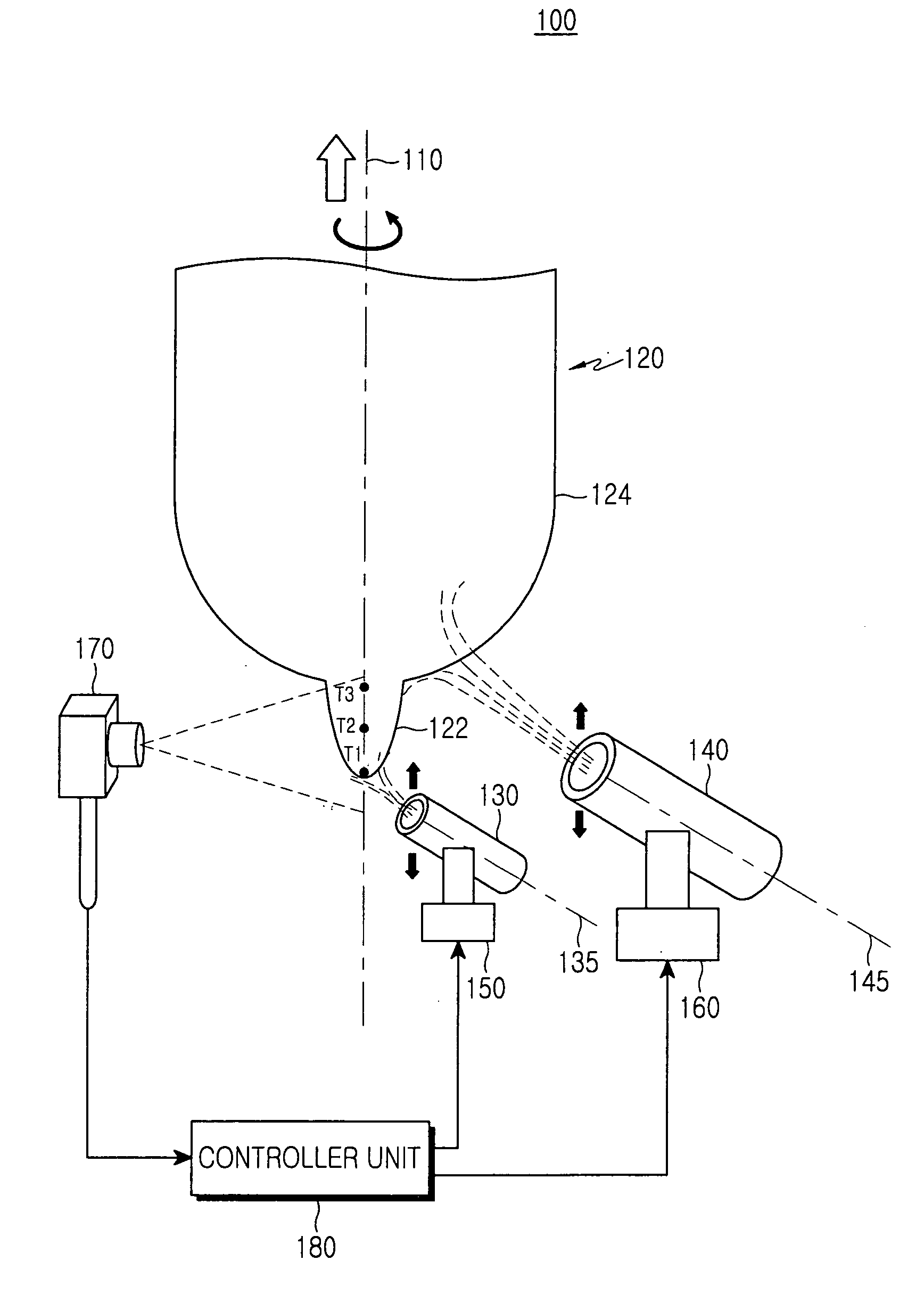
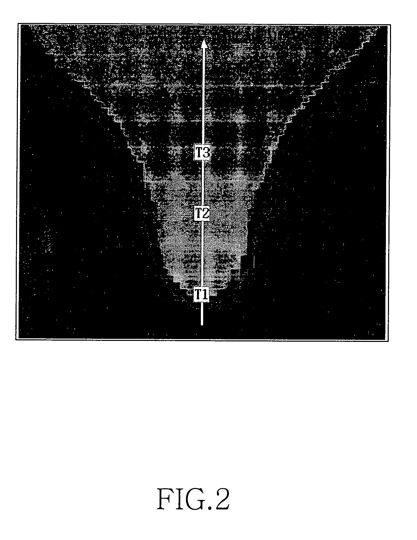
[0022]FIG. 1 illustrates a vapor axial deposition apparatus according to an embodiment of the present invention. The vapor axial deposition apparatus 100 includes first and second torches 130, 140 for creating and depositing soot, first and second stages 150, 160 for inclining the first and second torches, respectively, a temperature measuring unit 170 for detecting the temperature distribution of an end portion of a soot preform along a vertical axis 110, and a controller unit 180 for controlling the first and second to...


PUM

PropertyMeasurementUnit
Temperatureaaaaaaaaaa

Abstract

Disclosed is a vapor axial deposition apparatus. The vapor axial deposition apparatus includes a first torch, a second torch, a temperature measuring unit and a controller unit. The first torch deposits soot on a distal end of a soot preform aligned with a vertical axis to thereby grow a core. The second torch deposits soot on an outer circumferential surface of the core to thereby grow a clad. The temperature measuring unit detects the temperature distribution of an end portion of the soot preform along the vertical axis. The controller unit determines first and second relative maximum temperatures T1 and T3, and relative minimum temperature T2 between T1 and T3 in the detected temperature distribution, and controls T1 to be within a predetermined range and the greater one of the difference (T1−T2) and (T3−T2) to not exceed a predetermined temperature.

Description

RELATED APPLICATION [0001] This application is related to that patent application entitled “Vapor Axial Deposition Apparatus and Vapor Axial Deposition Method,” filed on Jul. 17, 2006 and afforded Ser. No. 11 / 487,846, by the US Patent and Trademark Office, which claims the benefit of the earlier filing date to that patent application filed in the Korean Industrial Property Office on Sep. 16, 2005, and assigned Serial No. 2005-86898, the contents of which are hereby incorporated by reference.CLAIM OF PRIORITY [0002] This application claims the benefit of the earlier filing date, pursuant to 35 USC 119, to that patent application entitled “Vapor Axial Deposition Apparatus and Vapor Axial Deposition Method,” filed in the Korean Intellectual Property Office on Oct. 19, 2005, and assigned Serial No. 2005-98699, the contents of which are hereby incorporated by reference. BACKGROUND OF THE INVENTION [0003] 1. Field of the Invention [0004] The present invention relates to an apparatus and a...

Claims


Application Information

Patent Timeline
IPC IPC(8): C03B37/07C03B37/018F27B1/26
CPCC03B37/0142C03B2207/64C03B2207/66C03B2207/70Y02P40/57C03B37/018
Inventor KIM, JIN-HAINGLEE, HO-JINDO, MUN-HYUNSEONG, JAE-HYEONKIM, YUN-HO
Owner SAMSUNG ELECTRONICS CO LTD
Why Eureka
Try Eureka