Apparatus for railway freight car coupler knuckle

Inactive Publication Date: 2007-04-19
SHARMA & ASSOCS
View PDF10 Cites 58 Cited by
  • Summary
  • Abstract
  • Description
  • Claims
  • Application Information

AI Technical Summary

Benefits of technology

[0007] Another object of the invention is to eliminate the dangerous and hazardous routine of train personnel walking between railcars to manually open the knuckles.
[0008]

Problems solved by technology

This contact will ultimately result in costly

Method used


Image

  • Apparatus for railway freight car coupler knuckle
  • Apparatus for railway freight car coupler knuckle
  • Apparatus for railway freight car coupler knuckle

Examples


first embodiment

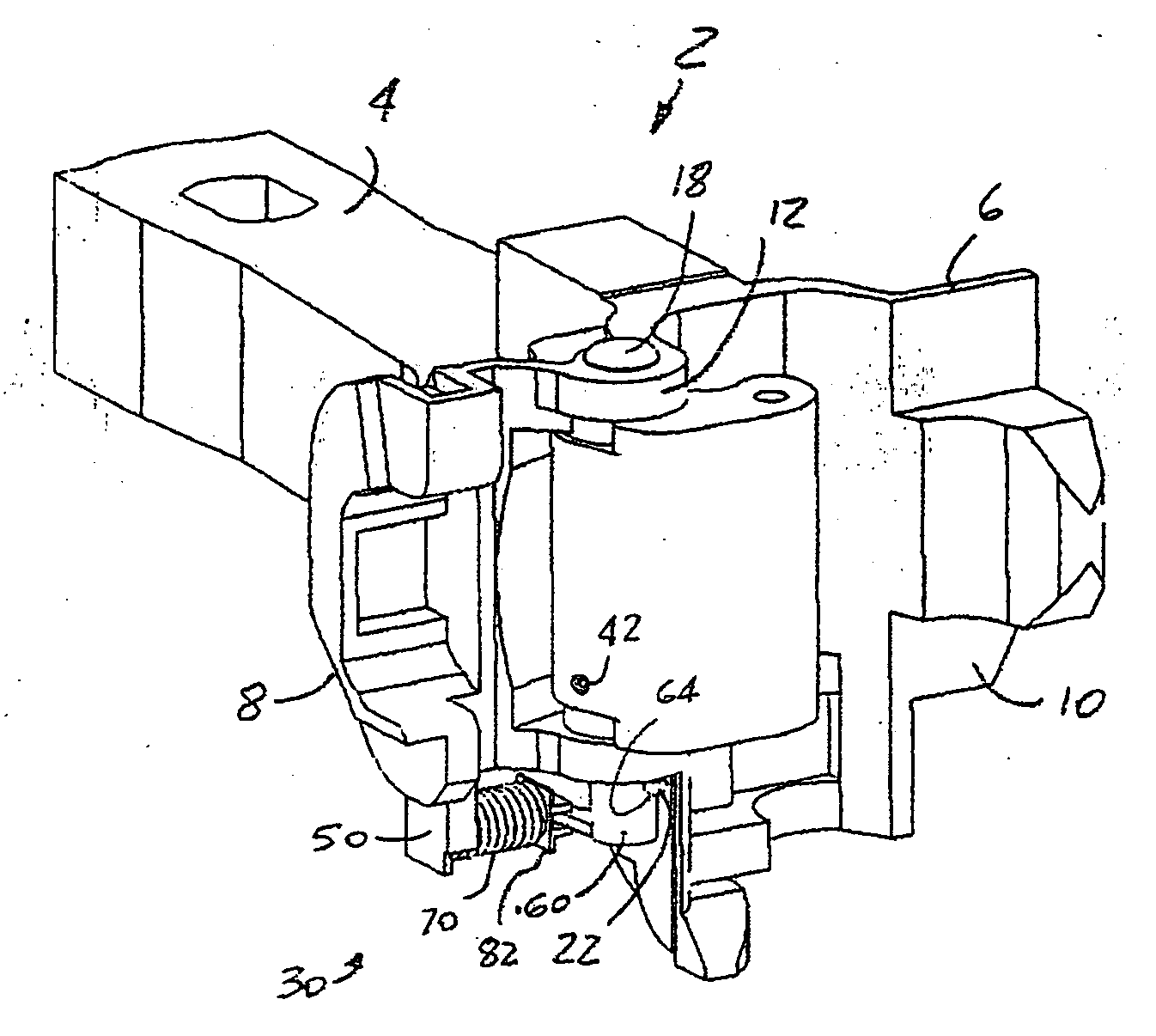
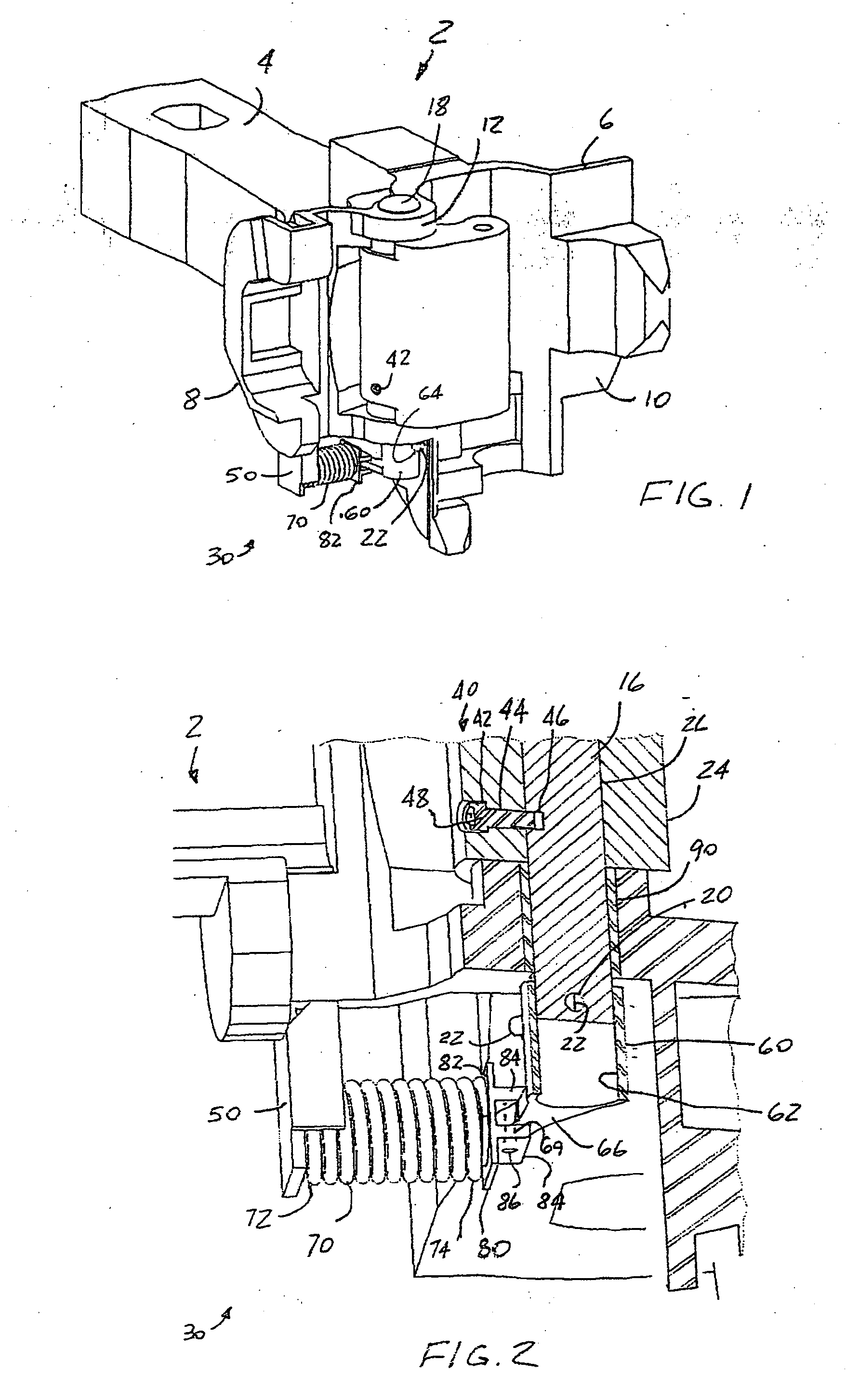
[0022] According to the invention, best shown in FIGS. 1-4, the improvement apparatus 30 includes a locking means, generally designated as 40 and best shown in FIG. 2, for rigidly securing such knuckle 24 to such knuckle pin 16 in order to prevent such independent rotation of such knuckle 24 relative to such knuckle pin 16, thus permitting simultaneous rotational motion of such knuckle 24 and such knuckle pin 16. It is presently preferred that such locking means 40 includes a locking aperture 42 which extends from the outer surface of the knuckle 24 to the wall of the aperture 26 and which has a longitudinal axis thereof disposed perpendicular to a longitudinal axis of such aperture 26 and such knuckle pin 16. The locking aperture 42 has a predetermined shape and has a threaded portion 44. There is a cavity 46 which is formed within the locking pin 16 and in alignment with the locking aperture 42 when such knuckle 24 is mounted onto such locking pin 16. A threaded fastener 48 thread...

second embodiment

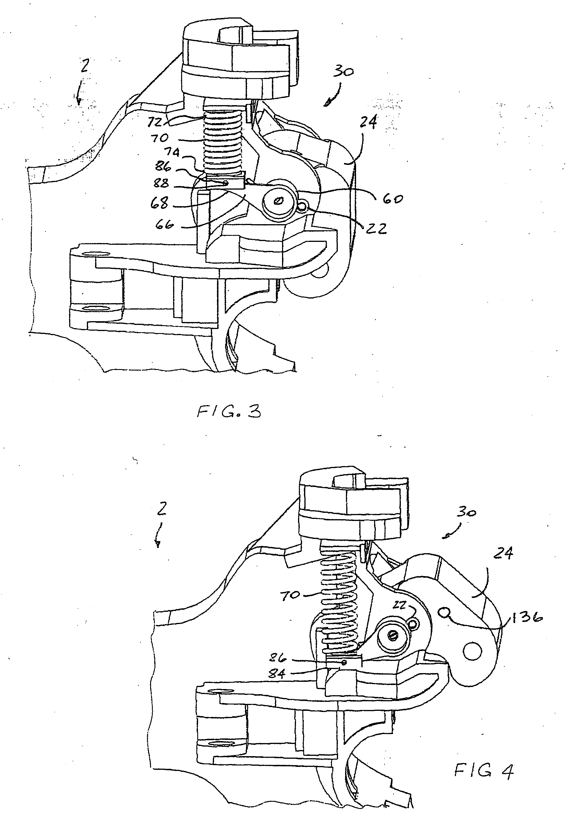
[0031] best shown in FIGS. 4-5, the improvement apparatus 30 includes a coiled torsion spring 100 capable of continuously exerting a predetermined force. The coiled torsion spring 100 has a coiled main portion 102, a first arm 104 which extends outwardly from one end of the coiled portion 102 and a second arm 106 which extends outwardly from an opposed end of the coiled portion 102.

[0032] The improvement apparatus 30 according to the second embodiment of the invention, also includes means, generally designated as 110, for attaching the coiled torsion spring 100 to a first portion of such coupler head 6 and, more particularly, to the knuckle side 8. Such means 110 includes an elongated sleeve member 112 which is coaxially engages a bottom end of such knuckle pin 16 at one end. A threaded aperture 114 is axially formed in such bottom end of such knuckle pin 16. A flange member 118 abuts a bottom end of the elongated sleeve member 112. A threaded fastener 120 threadably engages the th...


PUM


Abstract

In combination with a railway freight car coupler. A coupler has a knuckle side, and includes a knuckle, knuckle pin, and an apparatus for automatically pivoting and maintaining the knuckle full open position. The improvement comprises a coiled torsion spring which is capable of continuously exerting a predetermined force. A sleeve in combination with a flange is secured to the bottom end of the knuckle pin for attaching the torsion spring onto the coupler head. A support member is attached to the knuckle and cages one arm of the torsion spring which exerts a continuous force on the knuckle to rotate and maintain the knuckle full open position. A compression spring may be employed in place of the torsion spring in combination with a locking mechanism which, rigidly secures the knuckle and knuckle pin therebetween to prevent independent movement.

Description

CROSS-REFERENCE TO RELATED APPLICATIONS [0001] This application is related to and claims priority from Provisional Patent Application Ser. No. 60 / 728,021 filed Oct. 18, 2005.FIELD OF INVENTION [0002] The present invention relates, in general, to a railroad freight car coupler knuckle, and more particularly, to an apparatus for a railroad freight car coupler knuckle to automatically pivot and maintain the knuckle in the full open position. BACKGROUND OF THE INVENTION [0003] As is generally well known, all railroad freight cars are coupled together by mechanical couplers. The coupler consists of a coupler body, knuckle, and knuckle pin. To couple two cars, at least one of the coupler knuckles must be in the full open position. When contact between the knuckles is made, the coupling force will close the full open knuckle or knuckles. Freight car coupling systems are well known in the art. Several coupling system manufacturers include McConway & Torley, American Steel Foundries, and Col...

Claims


Application Information

Patent Timeline
IPC IPC(8): B61G3/00
CPCB61G3/08
Inventor BRABB, DAVID C.KANDOTH-KANNOTH, HARISH K.VITHANI, ANAND R.
Owner SHARMA & ASSOCS
Why Eureka
Try Eureka