Light-emitting device, planar light source and direct type backlight module

a technology of light-emitting devices and backlight modules, which is applied in the direction of lighting and heating apparatus, instruments, and semiconductor/solid-state device details, etc., can solve the problems of difficult and dangerous disposal of direct-type backlight modules, discontinuous light sources, and difficult to distinguish

Inactive Publication Date: 2007-04-19
HON HAI PRECISION IND CO LTD
View PDF6 Cites 59 Cited by
  • Summary
  • Abstract
  • Description
  • Claims
  • Application Information

AI Technical Summary

Benefits of technology

[0010] Compared with conventional CCFLs, this light-emitting device has following advantages. Quantum dot energy level in the light-emitting device can have different quantum levels. The bandwidth can be controlled in a more narrow way so that it is easier to distinguish between the individual light beams emitted from each quantum dot. Furthermore, light-emitting device having quantum dots are more environmentally friendly.

Problems solved by technology

Due to the spacing between the LCDs, the resulting light source is discontinuous.
The CCFLs may also have differences in brightness and chroma between each other such that the illumination of the direct type backlight module is poor.
As well as this, the CCFLs contain mercury, making them difficult and dangerous to dispose of safely.

Method used


Image

  • Light-emitting device, planar light source and direct type backlight module
  • Light-emitting device, planar light source and direct type backlight module
  • Light-emitting device, planar light source and direct type backlight module

Examples


Embodiment Construction

[0017] References will now be made to the drawings to describe preferred embodiments of the present light-emitting device, its related planar light source and direct type backlight module, in detail.

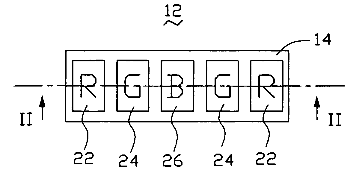
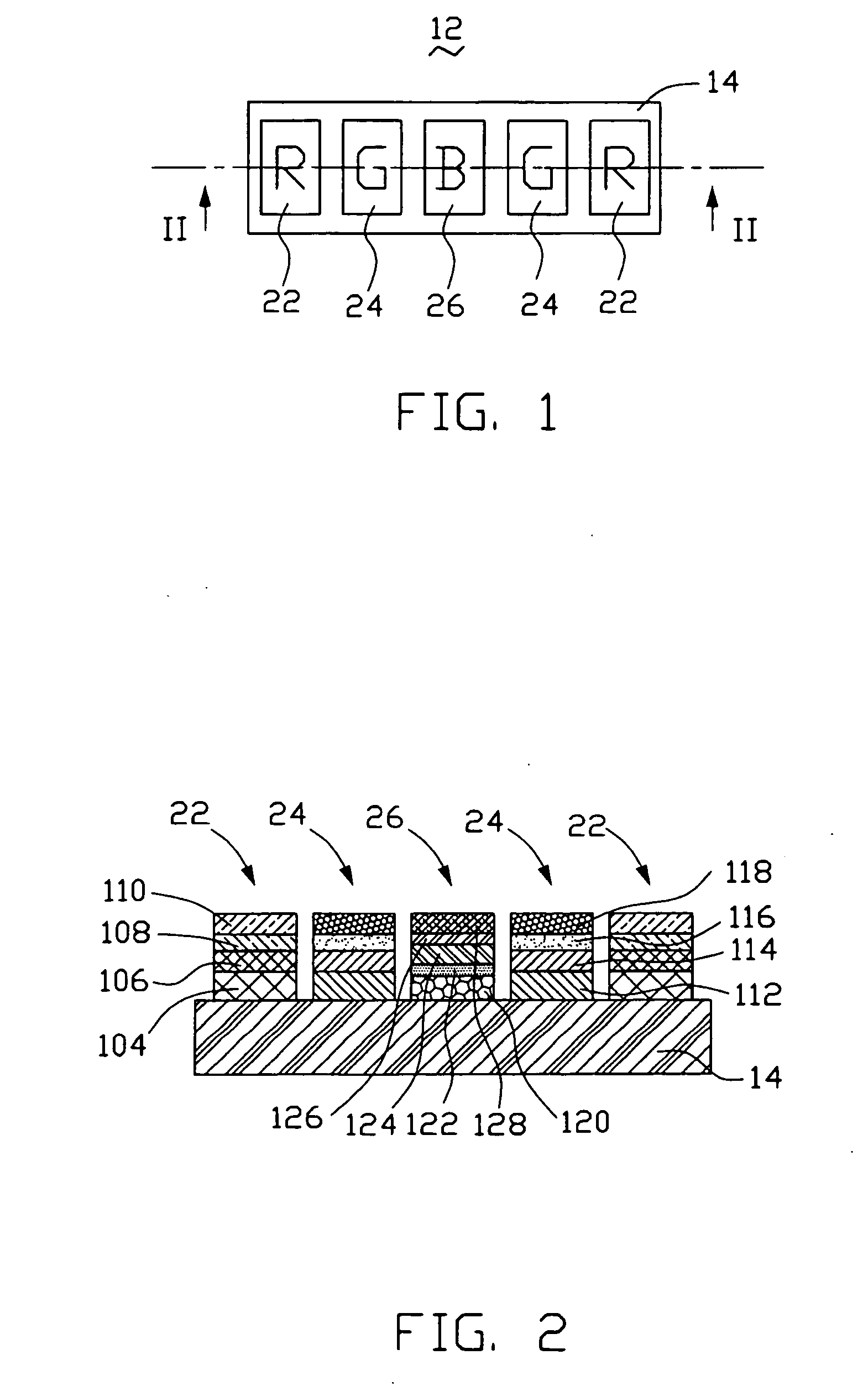
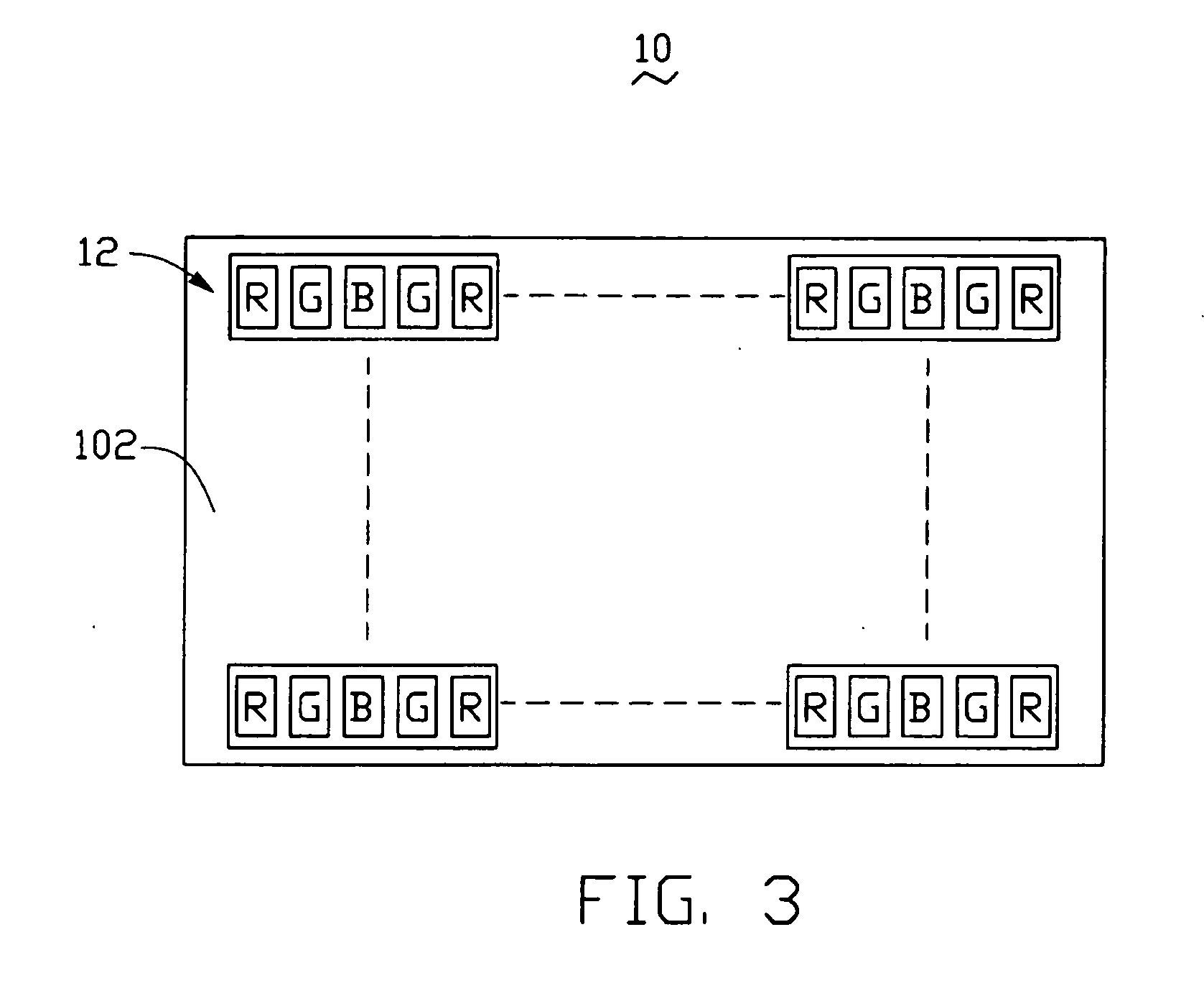
[0018] Referring to FIGS. 1 and 2, a light-emitting device 12 in accordance with a first embodiment is shown. The light-emitting device 12 includes a base 14, two red light-emitting chips 22, two green light-emitting chips 24 and a blue light-emitting chip 26.

[0019] The red light-emitting chips 22, the green light-emitting chips 24 and the blue light-emitting chip 26 are arranged on the base 14 in red-green-blue-green-red pattern from left to right. The red light-emitting chips 22, the green light-emitting chips 24 and the blue light-emitting chip 26 include a plurality of red-color quantum dots, green-color quantum dots and blue-color quantum dots respectively. The base 14 is made from glass plate or quartz glass plate.

[0020] The red light-emitting chip 22 includes a first semiconduc...


PUM


Abstract

A light-emitting device (12) includes a base (14) and two red light-emitting chips (22), two green light-emitting chips (24) and a blue light-emitting chip (26) arranged on the base red, green, blue, green, red in a left-to-right order. The red light-emitting chips, the green light-emitting chips and the blue light-emitting chip include a plurality of red-color quantum dots, green-color quantum dots and blue-color quantum dots respectively. A planar light source (10) includes a planar plate (102), and a plurality of the light-emitting devices arranged in an array on the planar plate. A direct type backlight module (20) includes a diffusing sheet (18) and the planar light source facing a surface of the diffusing sheet.

Description

BACKGROUND [0001] 1. Technical Field [0002] The invention generally relates to a light-emitting device, a planar light source and a direct type backlight module. [0003] 2. Discussion of Related Art [0004] Nowadays, liquid crystal materials are widely utilized in various liquid crystal displays (LCDs) having different sizes for different applications, such as TVs, liquid crystal projectors, mobile telephones, personal digital assistants (PDAs), etc. Since liquid crystal itself cannot emit light, light sources must be utilized to irradiate / illuminate liquid crystal for image display. The light sources are called backlight sources because they are usually configured behind liquid crystal panels. A combination of all components behind the liquid crystal panels, including the light sources, is generally referred to as a backlight module. Usually, backlight modules can be classified into edge type backlight modules and direct type backlight modules. [0005] Edge type backlight modules are ...

Claims


Application Information

Patent Timeline
Patent Type & Authority Applications(United States)
IPC IPC(8): H01L33/00H01L33/06
CPCB82Y10/00F21K9/00G02F1/133603H01L25/0753H01L33/06H01L2924/0002H01L2924/00
Inventor CHEN, GA-LANE
Owner HON HAI PRECISION IND CO LTD
Why Eureka
Try Eureka