Monitoring of alarm system wiring

a technology for monitoring and alarm systems, applied in the direction of electrical testing, measurement devices, instruments, etc., can solve the problem of not being able to activate all output devices when required

Active Publication Date: 2007-04-19
HONEYWELL INT INC
View PDF11 Cites 19 Cited by
  • Summary
  • Abstract
  • Description
  • Claims
  • Application Information

AI Technical Summary

Problems solved by technology

However, end of line resistors, and supervisory currents, as described above, while useful may not detect all such faults.
In such circumstances, while the system may appear to be fault free, it may not be able to activate all of the output devices when required.

Method used


Image

  • Monitoring of alarm system wiring
  • Monitoring of alarm system wiring
  • Monitoring of alarm system wiring

Examples


Embodiment Construction

[0019] While this invention is susceptible of embodiment in many different forms, there are shown in the drawing and will be described herein in detail specific embodiments thereof with the understanding that the present disclosure is to be considered as an exemplification of the principles of the invention and is not intended to limit the invention to the specific embodiments illustrated.

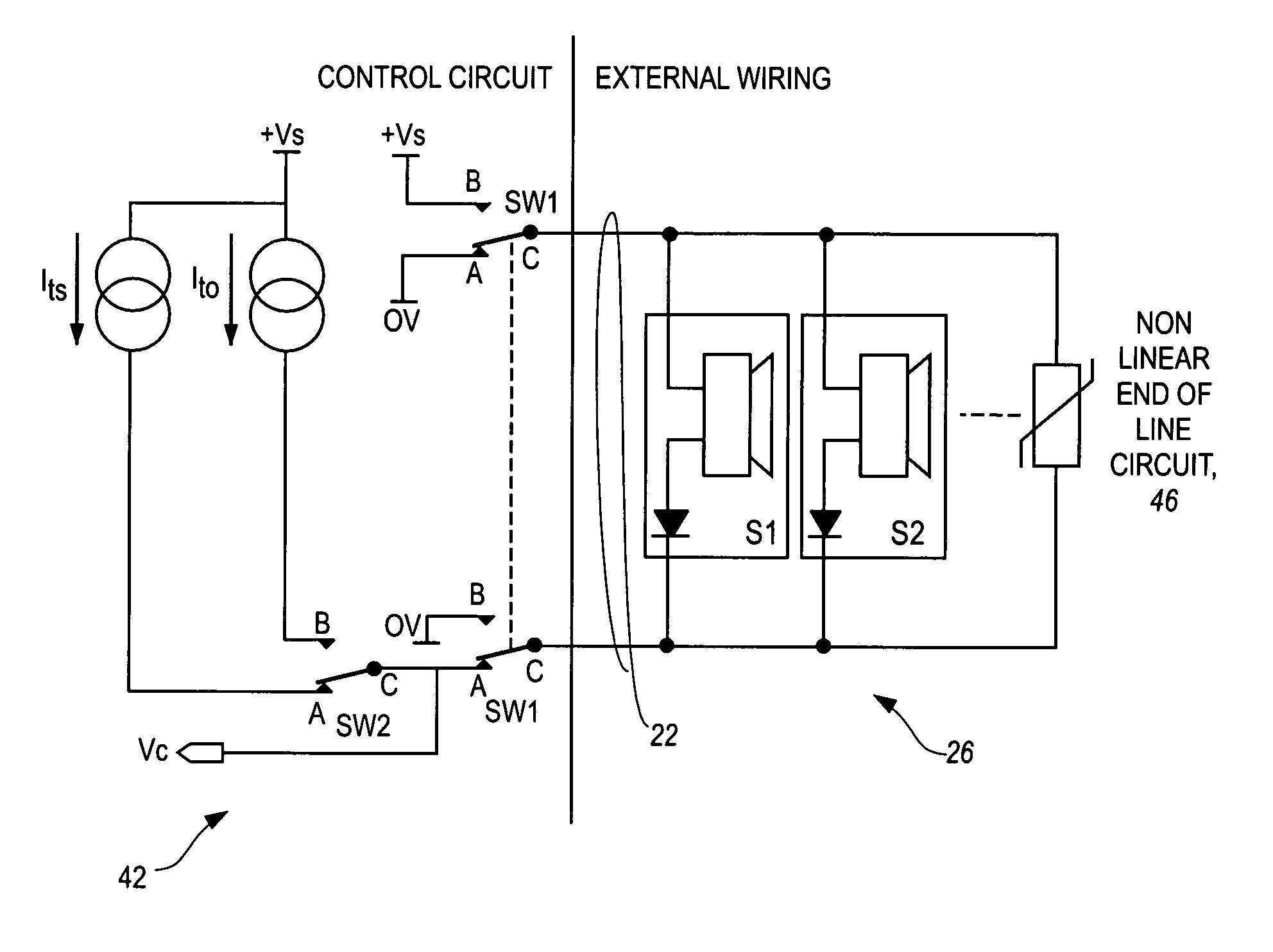
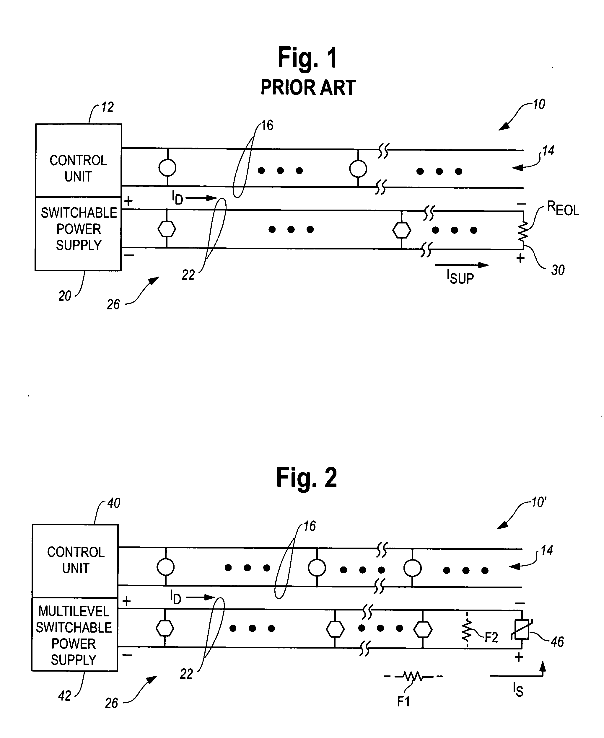
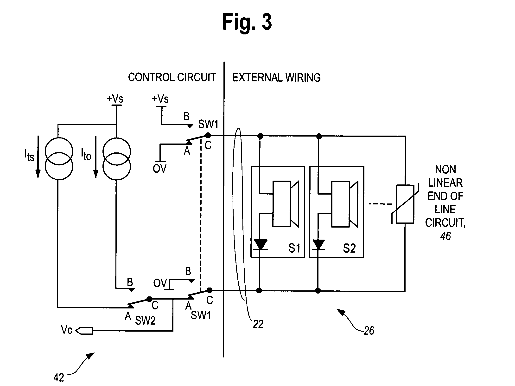
[0020] In one apparatus which embodies the invention, a non-linear or variable resistance element replaces the prior art resistor as the end of line element. For example, semi-conductor diodes, thermistors, transistors or the like can be used as alternates to fixed or known resistors.

[0021] In one aspect of the invention, a non-linear element could be connected as an end of line device across the lines of a spur with a polarity such that a monitoring current can only flow therethrough when a switched power supply associated with the loop is in a non-alarmed, supervisory state. When the power supp...


PUM


Abstract

A supervisory method and apparatus provide for detection of “partial fault” conditions such as a relatively high series impedance in the wiring, or a relatively low parallel impedance across the wiring. A non-linear element, such as a semiconductor diode, can be used as an end of line element. The element functions as a current controlled dynamic impedance such that currents through the element can be used to detect low parallel leakage currents. Higher currents through the element can be used to detect partial open circuits.

Description

FIELD OF THE INVENTION [0001] The invention pertains to ambient condition monitoring systems. More particularly, the invention pertains to such systems which incorporate additional supervisory circuitry to be able to monitor system wiring for open or short circuit faults. BACKGROUND OF THE INVENTION [0002] Many known alarm systems incorporate wired circuits for purposes of communicating with and / or providing electrical energy to various types of detectors and / or output devices such as sounders, strobe lights and the like all without limitation. The nature of such systems is such that a supervisory function is often provided for such wiring. Such are often monitored to determine if they are exhibiting either gross open circuit or short circuit conditions. [0003] One prior art solution has been to terminate the spur wiring with an end of line resistor. The value of the resistor is such that it will not affect operation of output appliances such as sounders or strobe lights or the like...

Claims


Application Information

Patent Timeline
Patent Type & Authority Applications(United States)
IPC IPC(8): G08B21/00G01R31/00
CPCG08B29/06
Inventor LARKIN, GARY N.
Owner HONEYWELL INT INC
Why Eureka
Try Eureka