

Display device and driving method thereof
- Summary
- Abstract
- Description
- Claims
- Application Information
AI Technical Summary
Benefits of technology
Problems solved by technology
Method used
Image

Examples
embodiment mode 2
[Embodiment Mode 2]
[0212] Although a capacitive line is separately provided in Embodiment Mode 1, it may be replaced by another wire which is already provided in the pixel. For example, the capacitive line can be omitted by using any one of the first to fourth scan lines. This embodiment mode describes a case where one of the first to fourth scan lines is used as a substitute for the capacitive line. Note that description will be made by using an EL element as an exemplary light-emitting element.
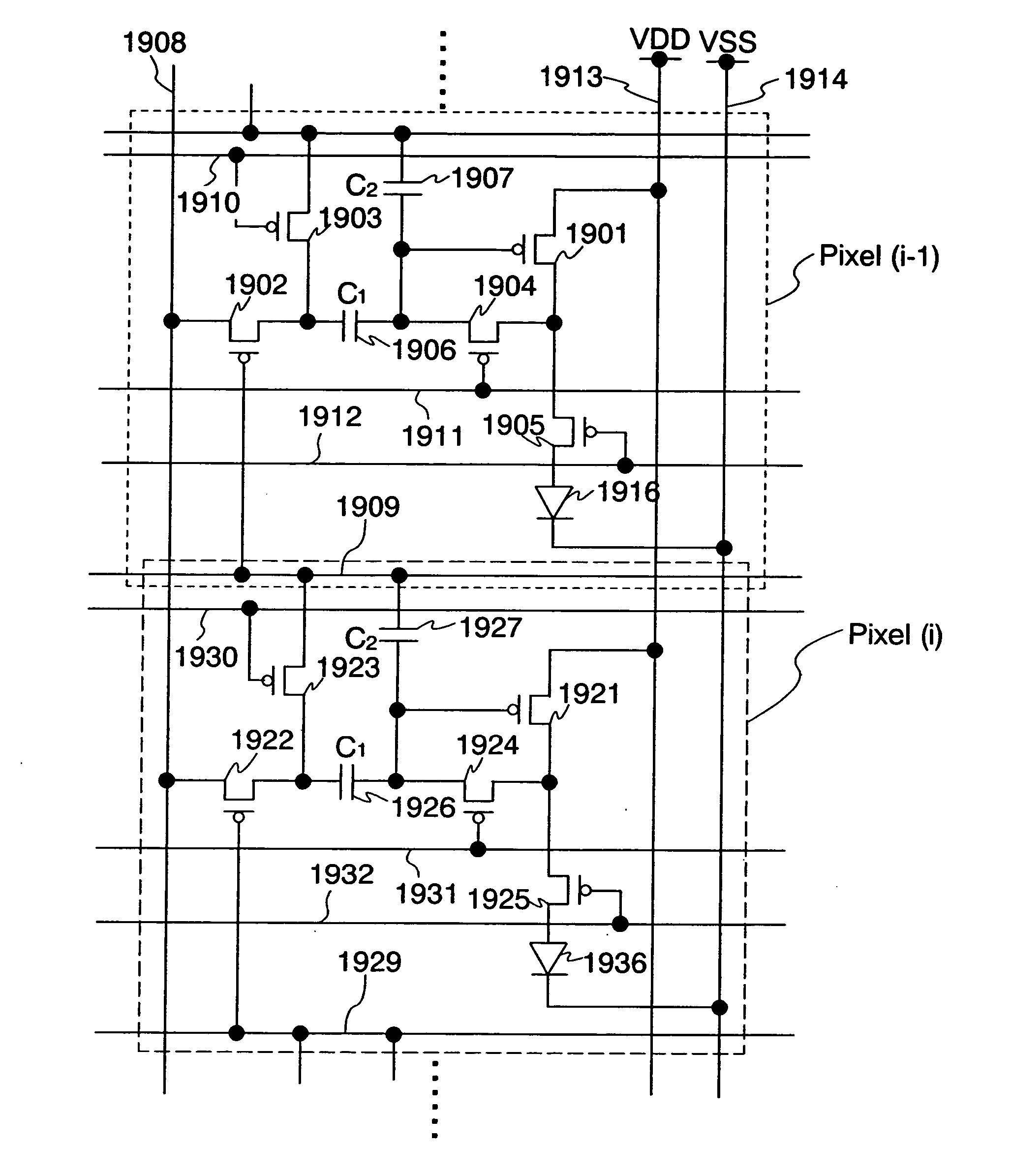
[0213] For example, FIG. 19 shows an exemplary pixel circuit in the case where the capacitive line in FIG. 3 is replaced by a first scan line in the preceding row. In FIG. 19, a first scan line 1909 of a Pixel (i−1) in an (i−1)-th row is used as a capacitive line of a Pixel (i) in an i-th row, and a second terminal of a third transistor 1923 and a second electrode of a second storage capacitor 1927 in the Pixel (i) in the i-th row are connected to the first scan line 1909 of the Pixel (i−1)...
embodiment mode 3
[Embodiment Mode 3]
[0222] Although a current is supplied to a light-emitting element for performing initialization in Embodiment Mode 1 and Embodiment Mode 2, initialization can be performed by adding an initialization transistor in the pixel circuit which is shown heretofore. In this embodiment mode, description will be made of a method of initialization using an initialization transistor. Note that description will be made by using an EL element as an exemplary light-emitting element.
[0223] In order to perform initialization, a second terminal of a first transistor is required to be set at an initialization potential. At this time, by connecting the second terminal of the first transistor to an electrode of another element or another wire through an initialization transistor, and then turning on the initialization transistor, the second terminal of the first transistor can be set at a potential of the electrode of the another element or the another wire.
[0224] That is, the initi...
embodiment mode 4
[Embodiment Mode 4]
[0249] Although the potential of the second power supply line is a fixed potential in Embodiment Mode 1 to Embodiment Mode 3, the potential of the second power supply line may be changed in accordance with the first period to the fourth period. In this embodiment mode, description will be made of a case where the potential of the second power supply line is changed in accordance with the first period to the fourth period. Note that description will be made by using an EL element as an exemplary light-emitting element.
[0250] For example, although the fifth transistor 305 in the pixel circuit shown in FIG. 3 is turned off to flow no current into the light-emitting element 316 in the second period T2 and the third period T3, a current supply to the light-emitting element 316 can be stopped by, for example, removing the fifth transistor 305 and directly connecting the second terminal of the first transistor 301 to the first electrode of the light-emitting element 316...
PUM
 Abstract
Description
Claims
Application Information