
Magnetic sensor control device

a control device and magnetic sensor technology, applied in the direction of instruments, liquid/fluent solid measurement, recording signal processing, etc., can solve the problems of inability to calculate highly accurate offsets, calculation errors, and point corresponding to magnetic data not form a perfect sphere, etc., to achieve efficient offset calculation

Inactive Publication Date: 2007-04-19
YAMAHA CORP
View PDF8 Cites 7 Cited by
  • Summary
  • Abstract
  • Description
  • Claims
  • Application Information

AI Technical Summary

Benefits of technology

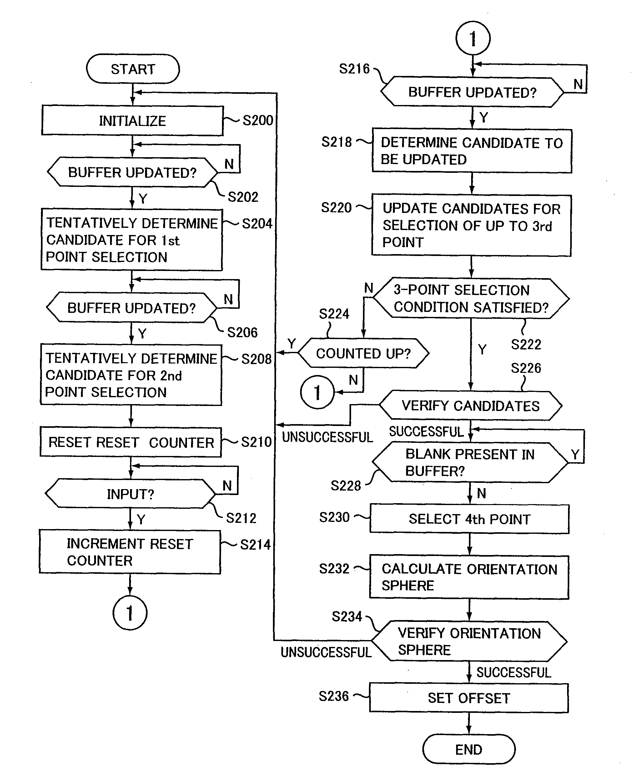
[0014] To ensure that 4 magnetic data satisfying the 4-point selection condition is selected from a plurality of magnetic data with one attempt, a large number of selections may be required and a large maximum amount of processing may be required for the selection. Thus, the selection condition is set in a stepwise manner and, before nth magnetic data is selected according to one condition, n−1th magnetic data is selected according to another condition, thereby reducing the maximum amount of processing required for the selection. In addition, when the nth magnetic data is selected according to one condition, magnetic data which has not been selected as any of up to the n−1th magnetic data is used again as a candidate for selection, thereby reducing the number of magnetic data required to calculate the offset. This reduces the number of manipulations of a moving body containing the 3D magnetic sensor, required to collect magnetic data to calculate the magnetic data offset and shortens the time required to calculate the offset.
[0069] Since 3 magnetic data satisfying a predetermined 3-point selection condition is selected from a plurality of magnetic data output sequentially from the 2D magnetic sensor, and a center point equally distant from 3 points corresponding to the 3 selected magnetic data is calculated, there is no need to use a statistical process in calculating the offset so that the offset can be calculated efficiently.

Problems solved by technology

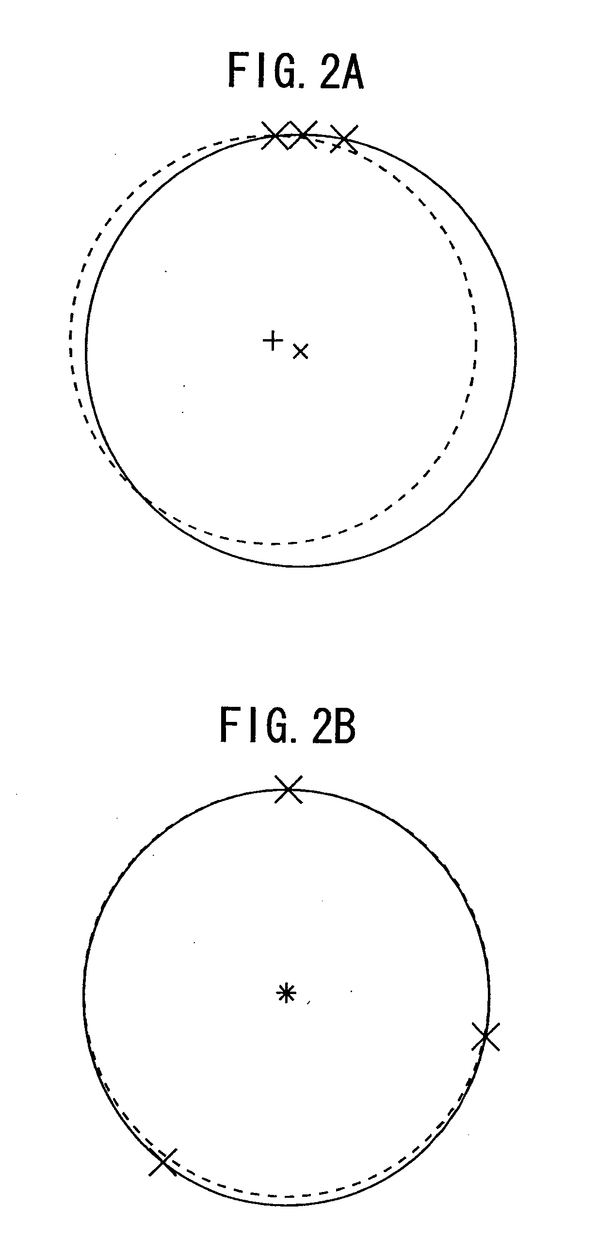
However, practically, a set of points corresponding to magnetic data do not form a perfect sphere.
The reasons are that outputs of the 3D magnetic sensor inherently have measurement errors following Gaussian distribution, a magnetic field measured by the 3D magnetic sensor varies during a period in which magnetic data required to calculate the offset is stored since in practice there is no completely uniform magnetic field, and calculation errors occur until digital values are obtained from the outputs of the 3D magnetic sensor.
However, when the statistical process of a large number of magnetic data is performed, a highly accurate offset cannot be calculated unless a magnetic data group as a statistical population is distributed evenly over a wide range and a peculiar magnetic data is excluded from the statistical population.
Accordingly, to calculate a highly accurate offset, it is necessary to select a statistical population and, ultimately, it is not possible to calculate a highly accurate offset only by the statistical process.
It also requires a very large amount of processing, a long time, and high resource consumption to calculate the most probable center of a spherical surface through the statistical process.
However, practically, a set of points corresponding to magnetic data do not form a perfect circle.
The reasons are that outputs of the 2D magnetic sensor inherently have measurement errors following Gaussian distribution, a magnetic field measured by the 2D magnetic sensor varies during a period in which magnetic data required to calculate the offset is stored since in practice there is no completely uniform magnetic field, and calculation errors occur until digital values are obtained from the outputs of the 2D magnetic sensor.
However, when the statistical process of a large number of magnetic data is performed, a highly accurate offset cannot be calculated unless a statistical population of magnetic data is distributed evenly over a wide range and a peculiar magnetic data is excluded from the statistical population.
Accordingly, to calculate a highly accurate offset, it is necessary to select a statistical population and, ultimately, it is not possible to calculate a highly accurate offset only by the statistical process.
It also requires a very large amount of processing, a long time, and high resource consumption to calculate the most probable center of a spherical surface through the statistical process.

Method used


Image

  • Magnetic sensor control device
  • Magnetic sensor control device
  • Magnetic sensor control device

Examples


first embodiment

[0092] A. First Embodiment

[0093] [1. Overview]

[0094] 1-1. Basic Principle

[0095] 1-2. Hardware Structure

[0096] 1-3. Software Structure

[0097] [2. Procedure]

[0098] 2-1. Buffer Update

[0099] 2-2. Tentative Determination of Candidate for Selection of 1st Point

[0100] 2-3. Tentative Determination of Candidate for Selection of 2nd Point

[0101] 2-4. Selection of up to 3rd Point [0102] 3-Point Update [0103] 3-Point Selection Condition [0104] Selection Verification [0105] 3-Point Reset

[0106] 2-5. 4th Point Selection [0107] Overview [0108] 4-Point Selection Condition [0109] Orientation Sphere Calculation [0110] Orientation Sphere Verification [0111] Offset Setting

second embodiment

[0112] B. Second Embodiment

[0113] [1. Overview]

[0114] 1-1. Basic Principle

[0115] First, a basic principle of the first embodiment is described.

[0116] This embodiment sets an offset to negate magnetization components of a moving body included in an output of a 3D magnetic sensor provided in the moving body. To obtain the offset, this embodiment specifies a spherical surface which approximates a 3D surface by a set of a number of points in a vector space having components corresponding to magnetic data output from the 3D magnetic sensor. This spherical surface will be referred to as a spherical surface of an orientation sphere. The coordinate components specifying the center point of the orientation sphere correspond to the offset, and the radius of the orientation sphere corresponds to the intensity of the magnetic field. Since there is an inherent measurement error in the output of the 3D magnetic sensor, a set of points represented by coordinate components corresponding to the 3 ...


PUM

PropertyMeasurementUnit
radiusaaaaaaaaaa
magneticaaaaaaaaaa
magnetic dataaaaaaaaaaa

Abstract

A magnetic sensor control device has an input section, a selection section, a calculation section, and a setting section. The input section inputs a plurality of magnetic data each having 3 components sequentially output from a 3-dimensional (3D) magnetic sensor. The selection section selects 4 magnetic data satisfying a predetermined 4-point selection condition from the plurality of the input magnetic data. The calculation section calculates a center point equally distant from 4 points corresponding to the 4 selected magnetic data. The setting section sets 3 components representing the center point as an offset of the magnetic data.

Description

BACKGROUND OF THE INVENTION [0001] 1. Technical Field of the Invention [0002] The present invention relates to a magnetic sensor control device, method, and program. [0003] 2. Description of the Related Art [0004] In a first aspect, a conventional 3-dimensional (3D) magnetic sensor mounted on a moving body detects the direction of an Earth's magnetic field (geomagnetism). The 3D magnetic sensor generally includes 3 magnetic sensor modules to detect scalar components of the magnetic field vector in 3 orthogonal directions. Magnetic data output from the 3D magnetic sensor has 3 components since the magnetic data consists of a combination of outputs of the 3 magnetic sensor modules. The direction and magnitude of a vector having components corresponding to the magnetic data corresponds to the direction and magnitude of a magnetic field detected by the 3D magnetic sensor. When specifying the direction or magnitude of an Earth's magnetic field based on outputs of the 3D magnetic sensor, ...

Claims


Application Information

Patent Timeline
Patent Type & Authority Applications(United States)
IPC IPC(8): G11B20/14
CPCG01C17/38G01R33/00
Inventor HANDA, IBUKI
Owner YAMAHA CORP
Learn More