Hot runner nozzle heater and methods of manufacture thereof

a hot runner nozzle and heater technology, applied in the field of electric heaters, can solve the problems of time-consuming and costly production of many hot runner nozzle heaters, and is difficult to remove for repair or replacemen

Active Publication Date: 2007-04-19
WATLOW ELECTRIC MFG
View PDF16 Cites 29 Cited by
  • Summary
  • Abstract
  • Description
  • Claims
  • Application Information

AI Technical Summary

Problems solved by technology

Such heaters have often proven difficult to remove for repair or replacement due to thermal expansion between the hot runner nozzle body and the external heater during operation.
Additionally, many hot runner nozzle heaters have been time consuming and costly to produce, in addition to demonstrating certain inefficiencies in providing the requisite temperature profiles along the length of the hot runner nozzle throughout a variety of different processing environments.

Method used


Image

  • Hot runner nozzle heater and methods of manufacture thereof
  • Hot runner nozzle heater and methods of manufacture thereof
  • Hot runner nozzle heater and methods of manufacture thereof

Examples


Embodiment Construction

[0028] The following description of the preferred embodiments is merely exemplary in nature and is in no way intended to limit the invention, its application, or uses.

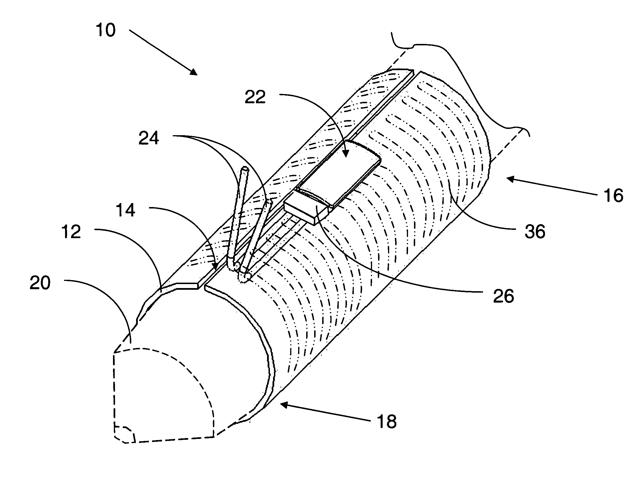
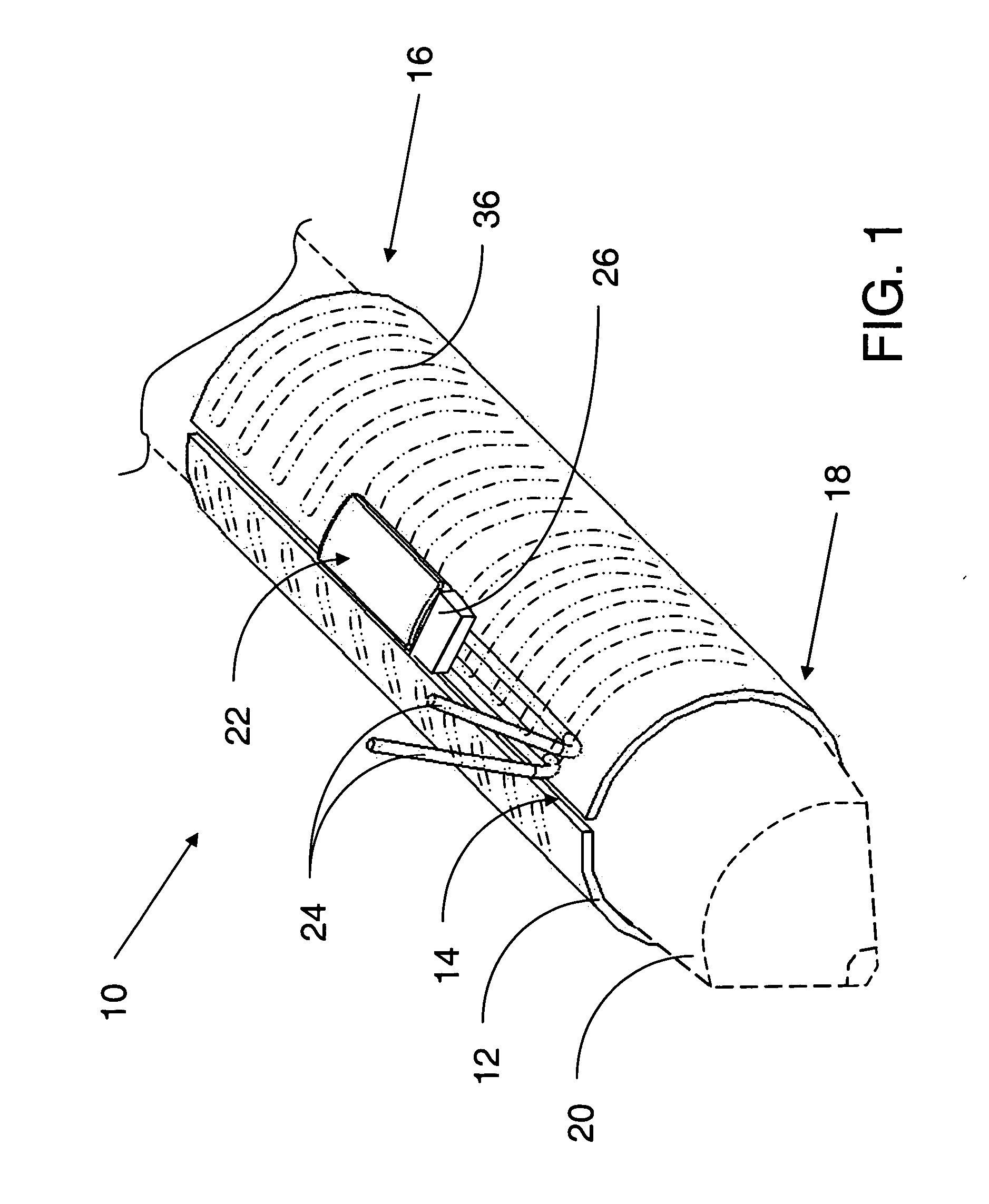
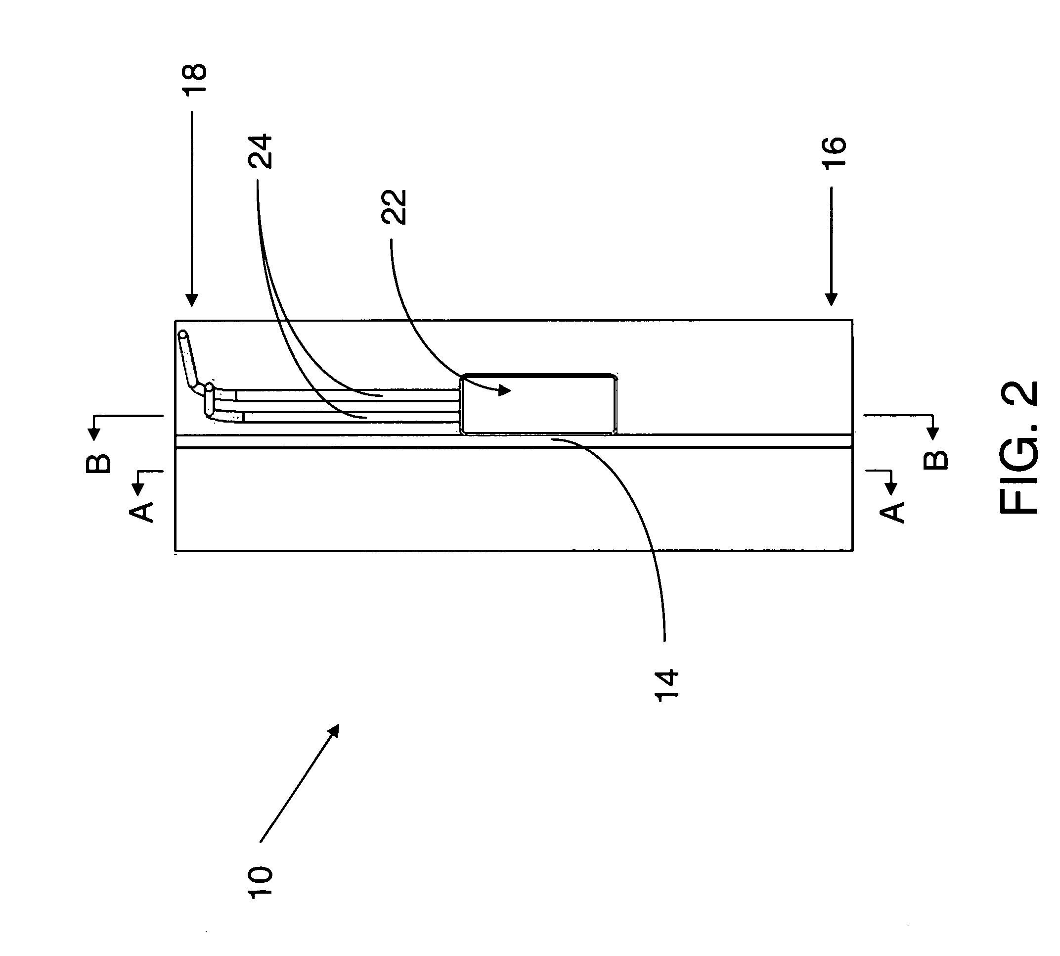
[0029] Referring to FIGS. 1-3, a hot runner nozzle heater in accordance with the present invention is illustrated and generally indicated by reference numeral 10. The hot runner nozzle heater 10 is preferably a layered heater and thus comprises a plurality of layers as described in greater detail below. As shown, the hot runner nozzle heater 10 in one form comprises a sleeve 12 defining a split-sleeve configuration, wherein the split in this specific embodiment is a slot 14 that extends along the length of the sleeve 12, from a proximal end 16 to a distal end 18. The hot runner nozzle heater 10 is specifically configured for placement around a cylindrical body such as a hot runner nozzle 20 (shown dashed) for injection molding equipment. Alternately, the hot runner nozzle heater 10 may comprise a geometry other than a...


PUM

PropertyMeasurementUnit
lengthaaaaaaaaaa
distanceaaaaaaaaaa
areaaaaaaaaaaa

Abstract

A hot runner nozzle heater is provided that includes a sleeve defining a slot extending along a length of the sleeve. A first dielectric layer is disposed over an outer surface of the sleeve, and a resistive element layer is disposed over the first dielectric layer, wherein the resistive element layer defines a resistive circuit pattern that is preferably formed by a laser trimming process. A pair of terminal leads are secured to a portion of the resistive element layer thus defining a termination area, and the termination area is positioned proximate the slot and away from the proximal end and the distal end of the sleeve. A second dielectric layer is disposed over the resistive element layer but not over the termination area, a third dielectric layer is disposed over the termination area, and a protective layer disposed over the second dielectric layer and the third dielectric layer.

Description

FIELD OF THE INVENTION [0001] The present invention relates generally to electrical heaters and more particularly to layered film heaters for use in hot runner nozzle applications in injection molding equipment. BACKGROUND OF THE INVENTION [0002] Layered heaters are typically used in applications where space is limited, where heat output needs vary across a surface, where rapid thermal response is desired, or in ultra-clean applications where moisture or other contaminants can migrate into conventional heaters. A layered heater generally comprises layers of different materials, namely, a dielectric and a resistive material, which are applied to a substrate. The dielectric material is applied first to the substrate and provides electrical isolation between the substrate and the electrically-live resistive material and also reduces current leakage to ground during operation. The resistive material is disposed on the dielectric material in a predetermined pattern and provides a resisti...

Claims


Application Information

Patent Timeline
Patent Type & Authority Applications(United States)
IPC IPC(8): F24H1/10B05B1/24B05B7/22B67D5/62B67D7/80
CPCB29C45/2737B29C2045/2746H05B3/56H05B3/565Y10T137/6416
Inventor RUSSEGGER, ELIASSCHEFBANKER, GERHARDANTOSCH, GERNOTPOSCHL, WOLFGANGLANHAM, CHRISTOPHER C.MCMILLIN, JAMESMCDOWELL, WILLIAM A. IIIFENNEWALD, KENNETH F.BOLDT, ALLENZIMMERMANN, FREDERICLEHNERT, REINHARDTPTASIENSKI, KEVIN
Owner WATLOW ELECTRIC MFG
Why Eureka
Try Eureka