Clipping circuit and radio transmitter using the same

a radio transmitter and clipping circuit technology, applied in the field of clipping circuit and radio transmitter using the same, can solve the problems of deteriorating bit error rate (ber) of the transmission path employed, the power amplifier with the favorable linearity for all transmissible amplitude values cannot be easily implemented, and the circuit consumption, so as to prevent the deterioration of the error vector magnitude of the modulated wave phase error. the effect of reducing phase error

Inactive Publication Date: 2007-04-19
NEC CORP
View PDF3 Cites 5 Cited by
  • Summary
  • Abstract
  • Description
  • Claims
  • Application Information

AI Technical Summary

Benefits of technology

[0015] In accordance with the present invention, by realizing the polygonal clipping in a simple circuit configuration, there can be obtained an advantage substantially equal to

Problems solved by technology

However, such a power amplifier with the favorable linearity for all transmissible amplitude values cannot be easily implemented in consideration of a circuit size, cost of the amplifier circuit, and power consumed by the circuit.
The output signal distorted in this manner interferes adjacent communication channels and deteriorates modulation accuracy, resulting in a deteriorated Bit Error Rate (BER) of a transmission path employed to send the signal.
Although the rectangular clipping is feasible by a

Method used


Image

  • Clipping circuit and radio transmitter using the same
  • Clipping circuit and radio transmitter using the same
  • Clipping circuit and radio transmitter using the same

Examples


Embodiment Construction

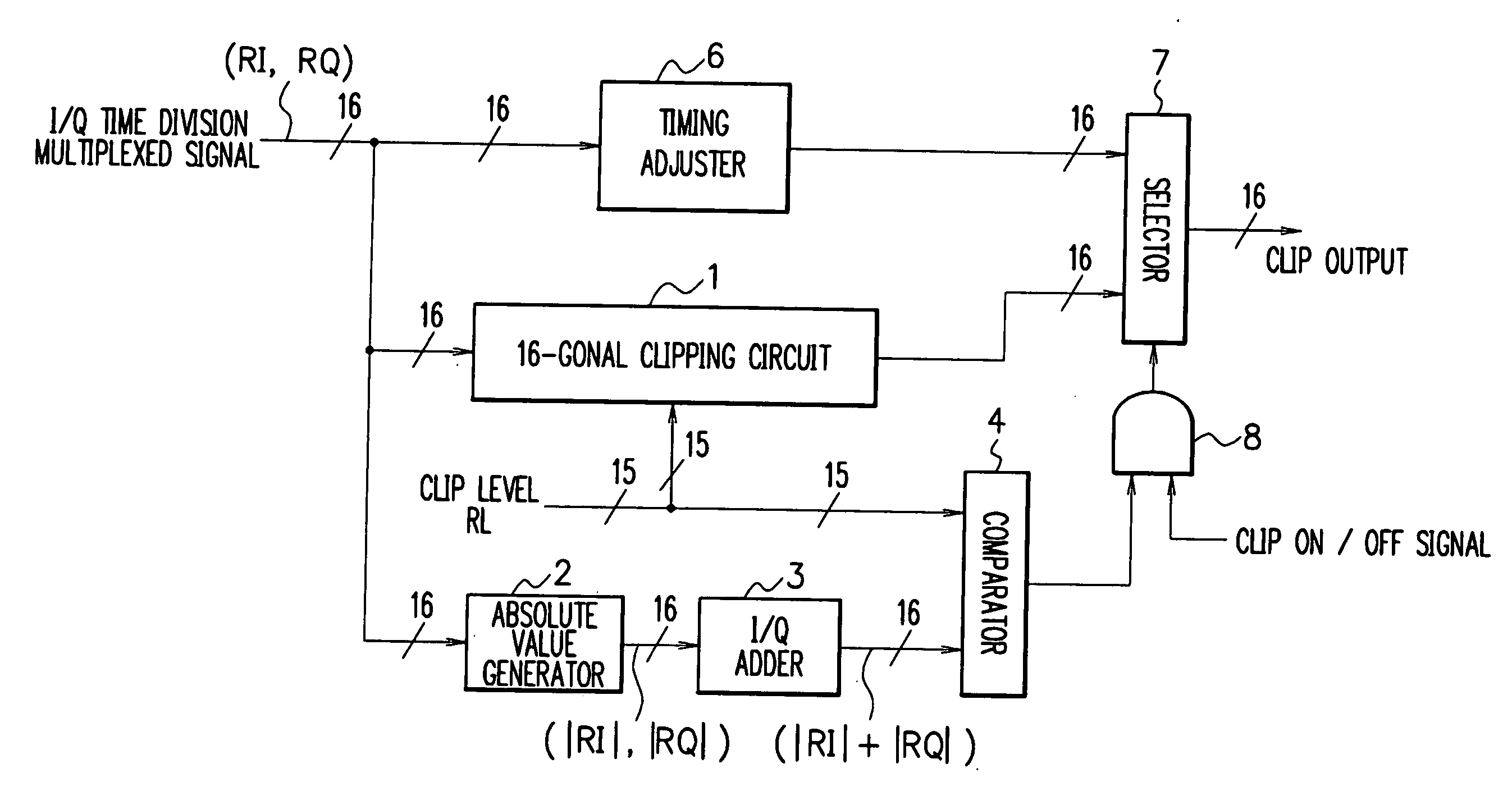
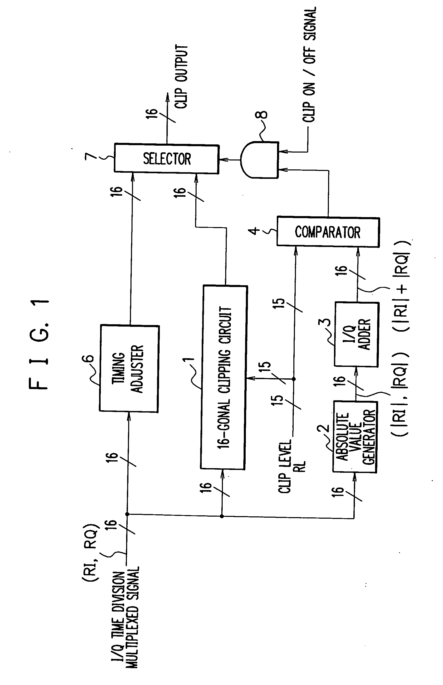
[0029] Referring next to the drawings, description will be given in detail of an embodiment in accordance with the present invention. FIG. 1 shows a block diagram of an embodiment of the present invention. In the configuration of FIG. 1, after a baseband signal is processed, orthogonal components of the baseband signal, i.e., an I component (RI) and a Q component (RQ) are fed to a timing adjuster 6, a 16-gonal clipping circuit 1, and an absolute value generator 2.

[0030] The generator 2 conducts an absolute value creating operation according to the I and Q components and delivers resultant signals to an adder circuit 3. The adder 3 adds the respective signals to each other to produce a signal, which is then fed to a comparator 4. The comparator 4 compares a value of amplitude of the baseband signal produced from the adder 3 with a signal level (a clip level=RL) beforehand determined for the clipping in the radio communication system. If the amplitude value of the baseband signal is ...


PUM


Abstract

A clipping circuit to limit amplitude of an orthogonal baseband signal includes a 16-gonal clipping circuit almost equivalent to a circular clipping circuit. The 16-gonal clipping circuit includes plural stages of series-connected units each including a rectangular clipping circuit and a phase rotating module. To compensate for variation in the signal amplitude due to the rectangular clipping circuits and the phase rotating modules, an amplitude adjuster conducts amplitude scaling for the signal.

Description

BACKGROUND OF THE INVENTION [0001] 1. Field of the Invention [0002] The present invention relates to a clipping circuit and a radio transmitter using the same, and in particular, to a clipping method for use in a radio transmitter for limiting the amplitude of orthogonal baseband signals supplied to a power amplifier in a radio transmitter. [0003] 2. Description of the Prior Art [0004] In a radio communication system, it is ideal on the side of a radio transmitter to use a power amplifier having an appropriate linear characteristic for all amplitude values of transmission signals. However, such a power amplifier with the favorable linearity for all transmissible amplitude values cannot be easily implemented in consideration of a circuit size, cost of the amplifier circuit, and power consumed by the circuit. There is hence employed in many cases a general power amplifier having linearity up to a particular amplitude and nonlinearity beyond the amplitude. [0005] When a power amplifier...

Claims


Application Information

Patent Timeline
IPC IPC(8): H04B1/02H04B1/04H03C1/52H04L27/20H04L27/26
CPCH04L27/2624
Inventor TERAMOTO, TOMOYUKI
Owner NEC CORP
Why Eureka
Try Eureka