Method for dynamically generating multiple views of three-dimensional models for utility networks

a utility network and three-dimensional model technology, applied in the field of computer software, can solve the problems of insufficient description or portrayal of the actual real-world parts being used, time-consuming and error-prone processes, and the editing process is thus quite tedious and laborious. to achieve the effect of improving the reliability and speed of editing

Active Publication Date: 2007-04-19
AUTODESK INC
View PDF1 Cites 26 Cited by
  • Summary
  • Abstract
  • Description
  • Claims
  • Application Information

AI Technical Summary

Benefits of technology

[0016] Additionally, a completed 3D model may be used to generate 2D construction and engineering documentation related to the model reflecting the attributes and properties of the parts included in the 3D model. Embodiments of the invention improve upon how parts are represented graphically, how parts are provided to users of a CAD application for composing the 3D model, and improve the reliability and speed of editing or revising 2D construction and engineering documentation. Thus, embodiments of the invention speed access to part editing and display of connected part properties and provide automatic updating of all views of the utility network as the utility model is changed (e.g., pipes added or removed, resized, moved to new orientation or depth. etc.). Editing of the model may be performed from any view thereof (e.g., a plan, a model or a profile view) and the results will automatically be reflected in other views of the utility network, without the user intervention required by current systems.

Problems solved by technology

The editing process is thus quite tedious and labor intensive.
Furthermore, the 2D graphics objects such as lines and curves only provide a crude representation of the network parts and thus the utility network and do not adequately describe or portray the actual real-world parts being used to construct the utility network.
Because modifications to 2D drawing objects (and any attributes or annotation labels) must be replicated individually within each view, the process is both time consuming and error-prone.
Accordingly, the crude 2D drawing objects fail to reflect the real-world characteristics of utility network components.

Method used


Image

  • Method for dynamically generating multiple views of three-dimensional models for utility networks
  • Method for dynamically generating multiple views of three-dimensional models for utility networks
  • Method for dynamically generating multiple views of three-dimensional models for utility networks

Examples


Embodiment Construction

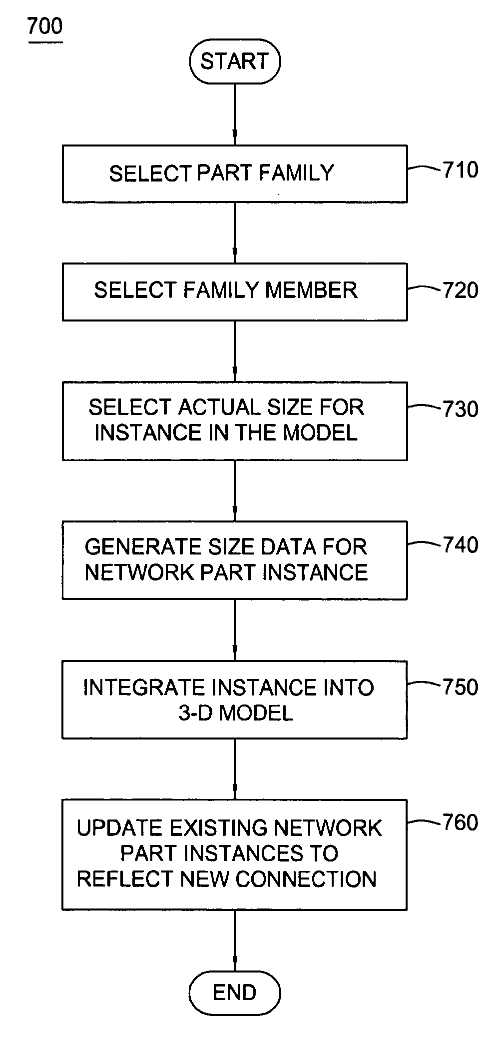
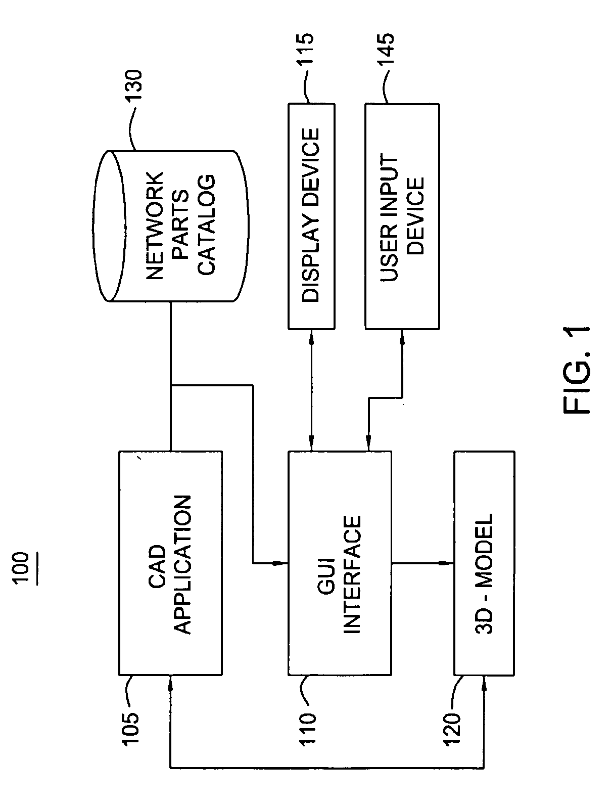
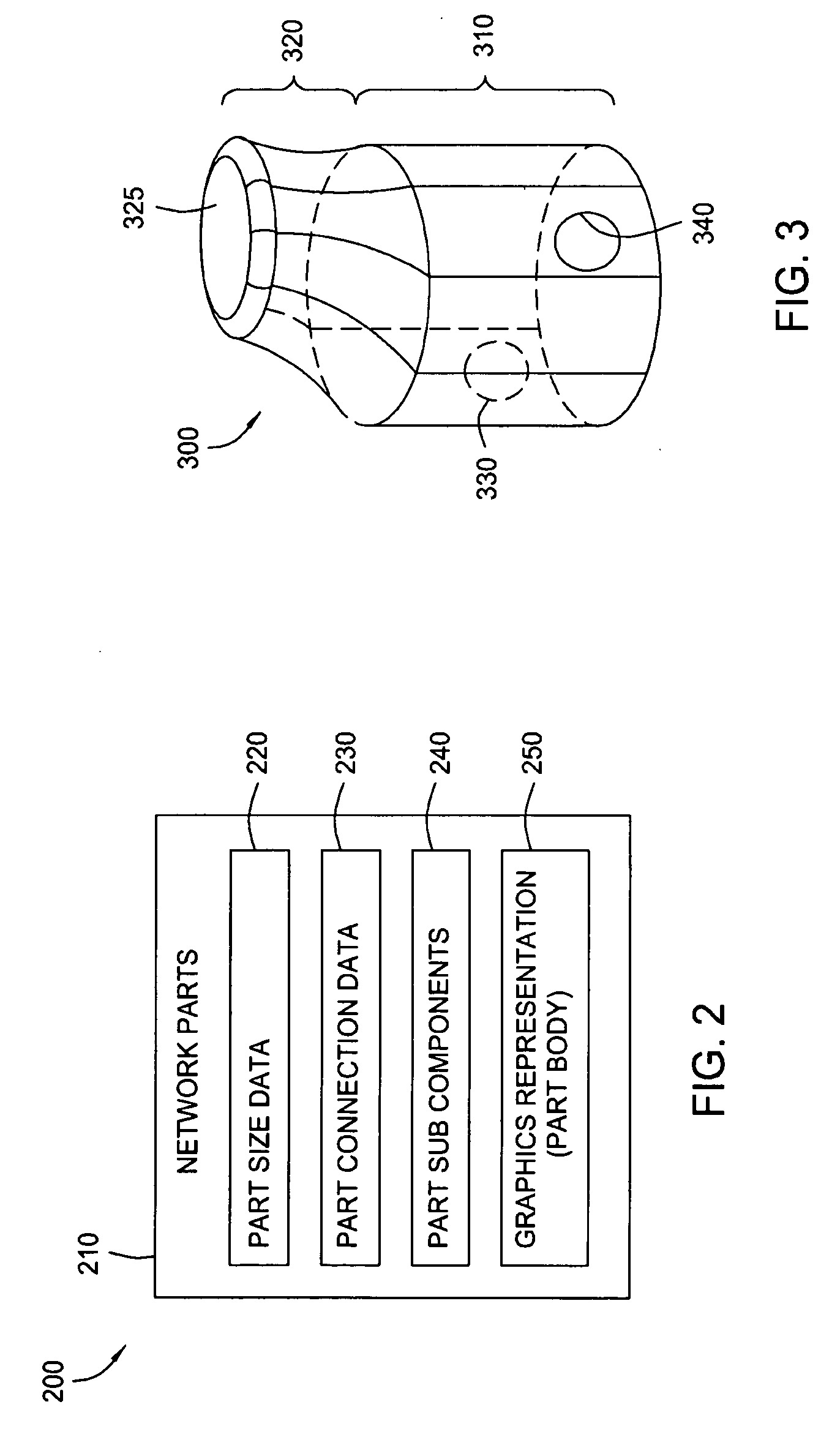
[0026] Embodiments of the invention provide a method, apparatus, and article of manufacture for creating a computer-generated three-dimensional model (3D model) of a utility network that is composed from many network part objects (or more simply, just “parts”). Each part inserted into a 3D model may correspond to a real-world component of a utility network. For example, embodiments of the invention may be used to model a utility network such as a gravity pipe system, etc using network parts such as pipes, manholes, catch basins and storm sewers. However, embodiments of the invention are not limited to modeling utility networks of any single type and may be extended to other utility networks. For example, embodiments of the invention described herein may be adapted to model utility networks such as telecommunications networks, pipeline networks, power grid networks etc.

[0027] In one embodiment, users of a CAD application may be provided with a catalog of network parts or part famili...


PUM


Abstract

Embodiments of the invention provide a method, apparatus and article of manufacture for modeling a variety of three-dimensional (3D) utility networks constructed from individual network part elements. In one embodiment, users may construct a utility network by selecting and assembling a network of inter-connected parts, where each part is selected from a pipe and structure list. Connectivity among parts is established through part placement. Structure and connected pipe properties may be managed as a single property set. As parts are placed in the utility network, auto-sizing logic resizes existing structures to connected pipes. Pipes and structures are represented by part model data that defines a set of common behavior and properties. When a user modifies part model data or property sets or moves inter-connected parts, a logic component resizes and automatically updates any associated two-dimensional and three-dimensional views of the utility network.

Description

BACKGROUND OF THE INVENTION [0001] 1. Field of the Invention [0002] The present invention generally relates to computer software. More specifically, the present invention relates to computer software applications configured to facilitate the interactive design of three-dimensional (3D) models of utility networks. [0003] 2. Description of the Related Art [0004] Currently, computer aided design (CAD) applications allow a designer or engineer to compose graphical representations of utility networks. For example, a user interacting with a CAD application may generate a model of a utility network by drawing simple 2D objects to represent components such as pipes, conduits, manhole covers, etc. Common 2D drawing objects include simple lines and arcs, etc. Additionally, some CAD applications may provide groupings of 2D objects used to model certain real-world structures (e.g., a collection of lines and ellipses to represent a cylinder). The user positions these 2D drawing objects relative ...

Claims


Application Information

Patent Timeline
Patent Type & Authority Applications(United States)
IPC IPC(8): G06F9/44
CPCG06F17/509G06F2217/34G06F30/18G06F2113/14
Inventor CONNOR, EDWARD JAMESSTORMS, CRAIGAPPOLO, MICHAEL A. IIIBURNHAM, TIMDEVAN, ANANDARAJAMILLIGAN, STEVEROGERSON, MICHAEL C.SPALDING, KENNETH W. III
Owner AUTODESK INC
Why Eureka
Try Eureka