Installation construction method for boiler facilities

a construction method and boiler technology, applied in the direction of fire-box steam boilers, heating types, steam separation arrangements, etc., can solve the problems of high construction costs, increased risk of workplace accidents, and large demand for reducing construction schedules, so as to achieve marked reduction of installation construction schedules

Active Publication Date: 2007-04-26
MITSUBISHI POWER LTD
View PDF7 Cites 12 Cited by
  • Summary
  • Abstract
  • Description
  • Claims
  • Application Information

AI Technical Summary

Benefits of technology

[0030] The present invention has been made to solve the aforementioned problems, and accordingly, it is an object of the present invention thereof to provide an installation construction method for boiler facilities wherein the installation construction schedule can be markedly reduced.
[0033] As described above, construction of the boiler building and completion of the boiler main unit are performed in parallel, so the installation construction schedule can be markedly reduced.

Problems solved by technology

This means that the work of carrying in and installing various types of equipment and accessories is concentrated in the period following completion of the boiler building, leading to problems in that all work regarding ducts, piping, and so on forth, is high-place work, meaning deterioration in work capability, and in that work within a limited space means work is restricted, requiring a longer construction schedule, and further that the amount of high-risk work at high places is great, leading to higher construction costs, and increased risk of workplace accidents.
Also, with arrangements wherein multiple members are combined to form a unit, and these are hoisted above the installation location using a crane and the lower for installation, already-assembled beams, columns, various types of equipment, accessory members, and the like, tend to interfere with carrying in and installing the units.
However, as of recent, there is great demand for reduction in the construction schedule from the perspective of cash flow and from the perspective of early electric power selling from starting operations early, and this demand cannot be met.
A particularly troublesome factor is how large the units can be manufactured and transported to the site.
However, this is not always the case, and road width may mandate the size of the units.
Not being able to transport giant-sized units to the site is a particular problem.

Method used


Image

  • Installation construction method for boiler facilities
  • Installation construction method for boiler facilities
  • Installation construction method for boiler facilities

Examples


Embodiment Construction

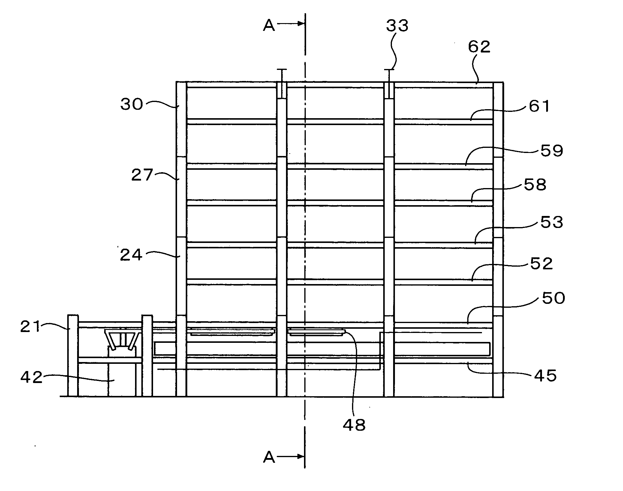
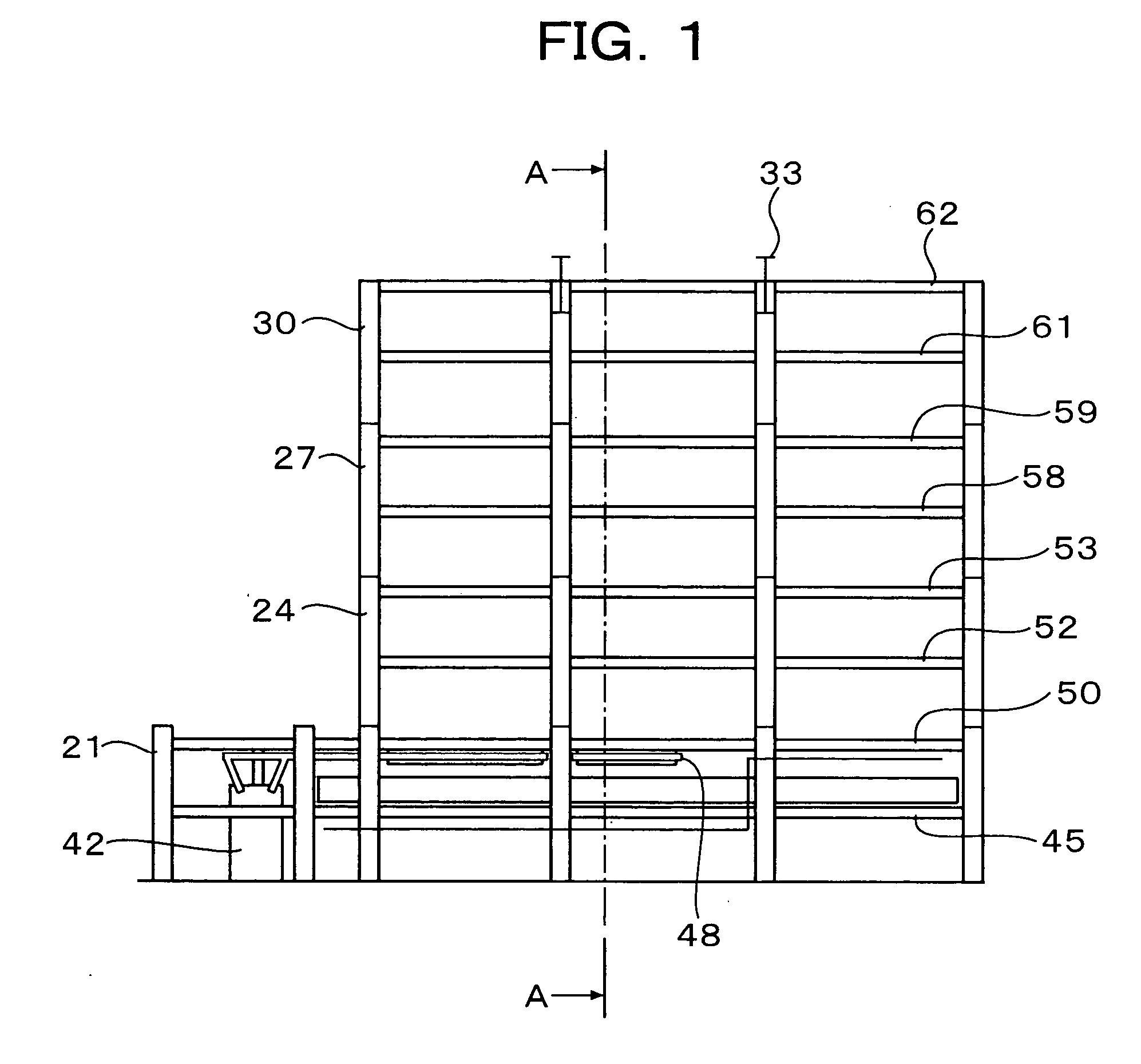
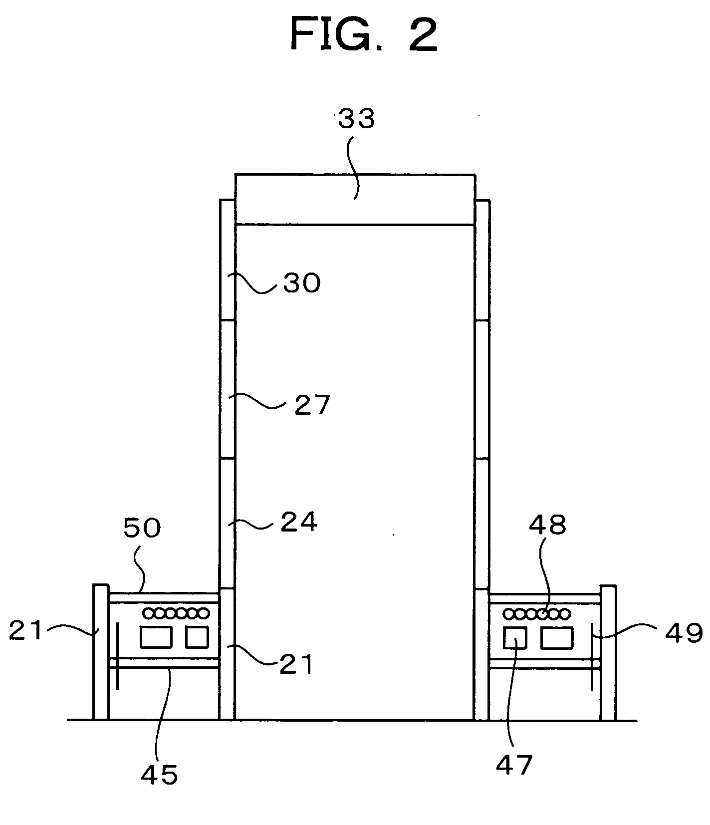
[0066] Next, an embodiment of the present invention will be described, with reference to the drawings. FIGS. 1 through 10 are schematic configuration diagrams for describing the boiler facilities installation construction method according to the present embodiment. In these drawings, FIGS. 2, 4, 6, 8, and 10, are views taken along line A-A in FIGS. 1, 3, 5, 7, and 9, respectively.

[0067] As shown in FIGS. 1 and 2, in the first zone 65, minimally required steel columns (first-level through fourth-level steel columns 21, 24, 27, 30) for suspending the boiler main unit are erected, first through eighth floor units 45, 50, 52, 53, 58, 59, 61, and 62 are installed between the minimally required steel columns (first-level through fourth-level steel columns 21, 24, 27, 30), and top girders 33 are disposed above the steel columns.

[0068] The minimally required steel columns (first-level through fourth-level steel columns 21, 24, 27, 30) for suspending the boiler main unit are the first-leve...


PUM

PropertyMeasurementUnit
particle sizeaaaaaaaaaa
temperatureaaaaaaaaaa
pressureaaaaaaaaaa

Abstract

With an installation construction method for boiler facilities, the boiler facilities comprise a boiler building configured of a steel structure, and a boiler main unit suspended within the boiler building from the upper portion of the boiler building. A portion of the boiler building is constructed, a portion of the boiler main unit is suspended from the upper portion of the partially-constructed boiler building, and while the remaining steel structure portions are being added to the partially-constructed boiler building so as to construct the boiler building, the remaining portions of the boiler main unit are added to complete the boiler main unit.

Description

BACKGROUND OF THE INVENTION [0001] 1. Field of the Invention [0002] The present invention relates an installation construction method for boiler facilities, and particularly relates to an installation construction method wherein the installation construction schedule can be markedly reduced. [0003] 2. Description of the Related Art [0004]FIG. 11 is a schematic configuration diagram of a common boiler facility for electric power production. A boiler main unit 1 is disposed within a boiler building 3 configured of a steel structure 2 around and above, and is suspended from top girders 4 traversing the top of the boiler building 3 by sling bolts. [0005] Secondary air for combustion to the boiler main unit 1 is guided to a furnace combustion chamber with a burner, via a forced draft fan, an air pre-heater 5, a wind box 6, and so on forth. Also, coal fuel transporting air is guided from the air pre-heater 5 to a mill 8 via a primary air duct 7. [0006] Coal to serve as fuel is stored in a...

Claims


Application Information

Patent Timeline
Patent Type & Authority Applications(United States)
IPC IPC(8): B23P21/00B21D51/16
CPCE04H5/02F22B37/24F22B37/244Y10T29/49387Y10T29/49904Y10T29/49352Y10T29/49345Y10T29/4935
Inventor TATEHIRA, KAZUKIMACHIDA, YUKITAKAMARIYAMA, TADAYOSHI
Owner MITSUBISHI POWER LTD
Why Eureka
Try Eureka