
Method of inspecting the profile of a connection zone between a cylindrical portion and a taper of a turbomachine part

Inactive Publication Date: 2007-04-26
SN DETUDE & DE CONSTR DE MOTEURS DAVIATION S N E C M A
View PDF5 Cites 4 Cited by
  • Summary
  • Abstract
  • Description
  • Claims
  • Application Information

AI Technical Summary

Benefits of technology

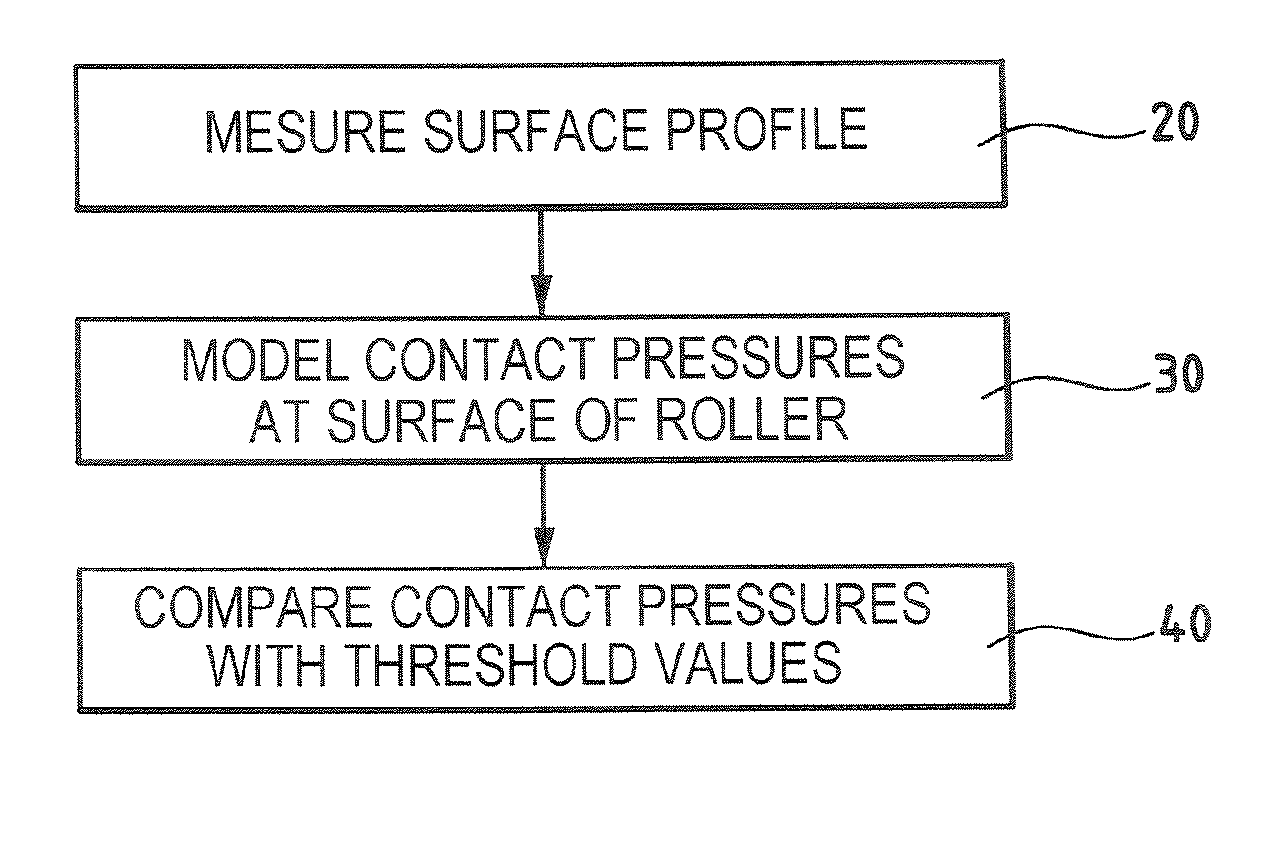
[0005] A main object of the present invention is thus to mitigate such drawbacks by proposing a method making it possible not only to inspect the profile of the connection zone between the cylindrical portion and the taper of a roller for a roller bearing, but also to determine the suitability of an arbitrary complex shape for performing the function of distributing pressure.
[0007] The method of the invention makes it possible to model the contact pressures that apply to the surface of the part by simple processing of the points of the profile as measured. It is thus possible to perform reliable quality control on the profile of a bearing roller, and in particular on the quality of the connection zone between the taper and the cylindrical portion of the roller.

Problems solved by technology

The rolling elements in the bearings used in turbomachines are subjected to operating conditions that are becoming ever more severe.
Although the number of failures encountered is constantly decreasing, the cost of such incidents remains high and the target of zero failures must be aimed for when designing a bearing.
The connection zones between the two tapers and the cylindrical portion of such a roller can nevertheless themselves give rise to contact stresses that are unacceptable in terms of reliability of contact between the roller and the raceways.
The amplitudes of such excessive stresses vary depending on the shapes of the connection zones as actually made during manufacture, and they have a direct influence on the risk of a roller flaking.
Unfortunately, standard measurement equipment does not enable such connection zones to be inspected.
Most instruments are limited to characterizing profiles that are simple and unique (such as profiles that are plane, circular, spherical, or cylindrical), and they are not suitable for handling combined profiles (i.e. combinations of simple profiles) in reliable manner, and they are even less suitable for handling the arbitrary profiles that can be obtained with present-day manufacturing means and that are associated with the connection zones between the tapers and the cylindrical portion of a roller.

Method used


Image

  • Method of inspecting the profile of a connection zone between a cylindrical portion and a taper of a turbomachine part
  • Method of inspecting the profile of a connection zone between a cylindrical portion and a taper of a turbomachine part
  • Method of inspecting the profile of a connection zone between a cylindrical portion and a taper of a turbomachine part

Examples


Embodiment Construction

[0017] In the description below, the context is that of inspecting the profile of the surface of a cylindrical roller for a turbomachine roller bearing. Nevertheless, the invention is applicable to inspecting the profiles of the surfaces of turbomachine parts other than rollers, whenever such parts are subjected to contact pressures and include a cylindrical portion connected to a taper (this could apply for example to blade roots where accurate profiles are essential).

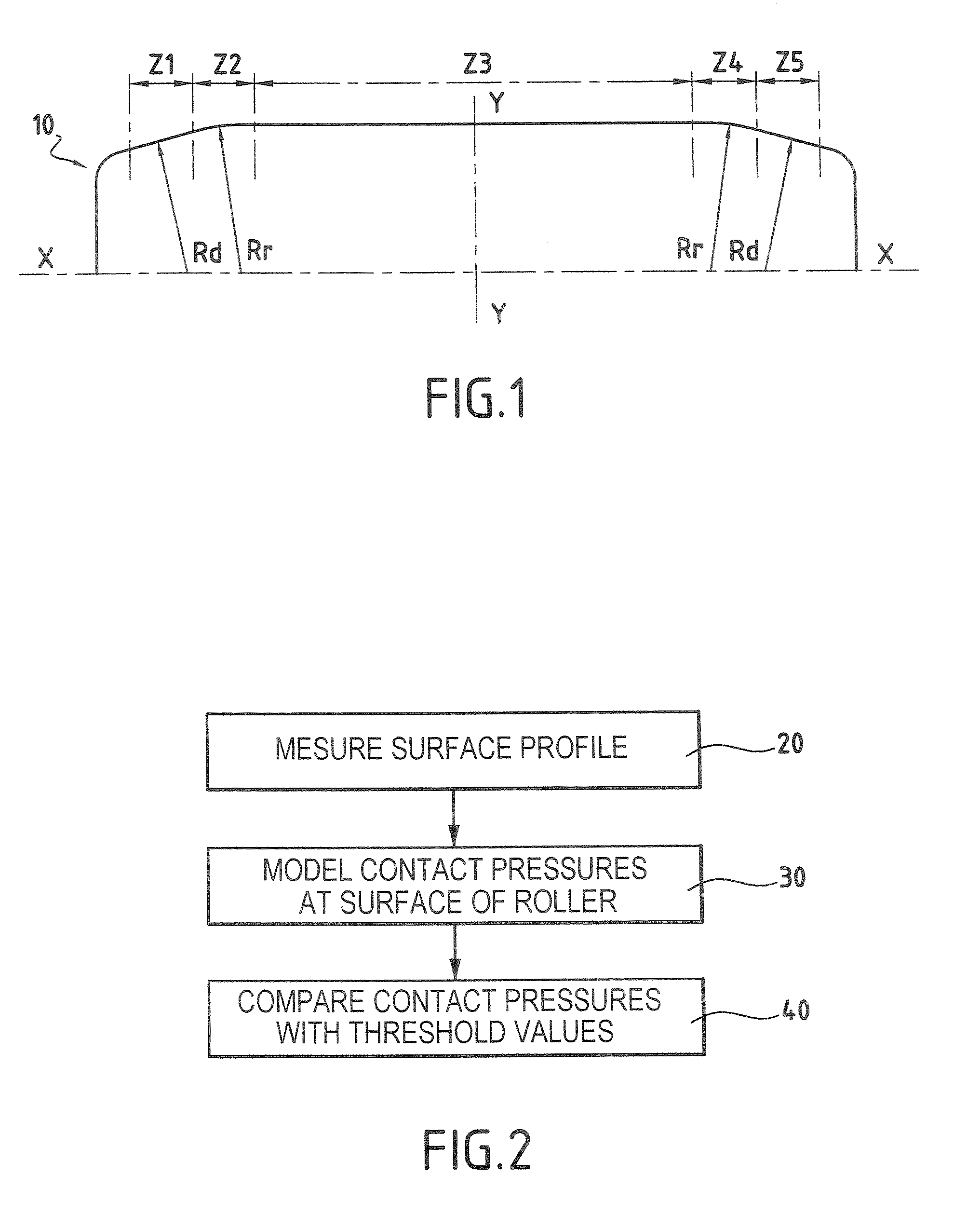
[0018] As shown in FIG. 1, it is assumed initially that the surface profile of a cylindrical roller 10 for a turbomachine roller bearing can be defined geometrically as follows: two first zones Z1 and Z5 corresponding to two tapers of the roller; two second zones Z2 and Z4 each corresponding to the connection between the cylindrical portion and a respective one of the tapers of the roller; and a third zone Z3 correspond to the cylindrical portion of the roller.

[0019] The cylindrical roller 10 is symmetrical, firstly...


PUM


Abstract

A method of inspecting the profile of the connection zone between the cylindrical portion and the taper of a turbomachine part, the surface profile of the part being geometrically defined by at least one first zone corresponding to the taper of the part, at least one second zone corresponding to the connection between the cylindrical portion and the taper of the part, and a third zone corresponding to the cylindrical portion of the part, the method consisting in measuring the surface profile of the part; from the measured surface profile, modeling the contact pressures that apply to the surface of the part for each of its zones; and comparing the contact pressures modeled for the second zone of the surface profile of the part with predefined threshold values.

Description

BACKGROUND OF THE INVENTION [0001] The present invention relates to the general field of quality control when inspecting the profile of turbomachine parts that are subjected to contact pressures, and in particular the cylindrical rollers used in the roller bearings of a turbomachine. [0002] Rolling bearings are commonly used in the field of aviation. In a turbomachine, rolling bearings serve in particular to support a first shaft in rotation relative to a stator or relative to a second shaft that is coaxial with the first. Such bearings are essentially constituted by balls or cylindrical rollers held in raceways formed by outer and inner rings. In general, ball bearings are used to take up axial loads while roller bearings are used to take up radial loads in a turbomachine. [0003] The rolling elements in the bearings used in turbomachines are subjected to operating conditions that are becoming ever more severe. Although the number of failures encountered is constantly decreasing, th...

Claims


Application Information

Patent Timeline
IPC IPC(8): G01M1/00
CPCF16C33/34F16C2240/50G01B21/20G01M13/04
Inventor PLONA, DANIEL GEORGES
Owner SN DETUDE & DE CONSTR DE MOTEURS DAVIATION S N E C M A
Learn More