
Wake stabilization device and method for reducing the aerodynamic drag of ground vehicles

a stabilization device and ground vehicle technology, applied in the direction of roofs, liquid/fluent solid measurements, instruments, etc., can solve the problems of unsteady and dynamic wake flow, inability to energize and stabilize low energy flow at and inability to stabilize low energy flow at the trailing edges of side surfaces. , to achieve the effect of minimizing aerodynamic drag, improving vehicle operation, and being convenient and convenient to us

Inactive Publication Date: 2007-04-26
WOOD RICHARD MICHAEL
View PDF24 Cites 27 Cited by
  • Summary
  • Abstract
  • Description
  • Claims
  • Application Information

AI Technical Summary

Benefits of technology

[0040] (s) to have no impact on operational requirements.
[0041] Further objects and advantages are to provide a device that can be easily and conveniently used to minimize aerodynamic drag on any ground vehicle for the purposes of improving the operational performance of the vehicle. Still further objects and advantages will become apparent from a consideration of the ensuing description and drawings.

Problems solved by technology

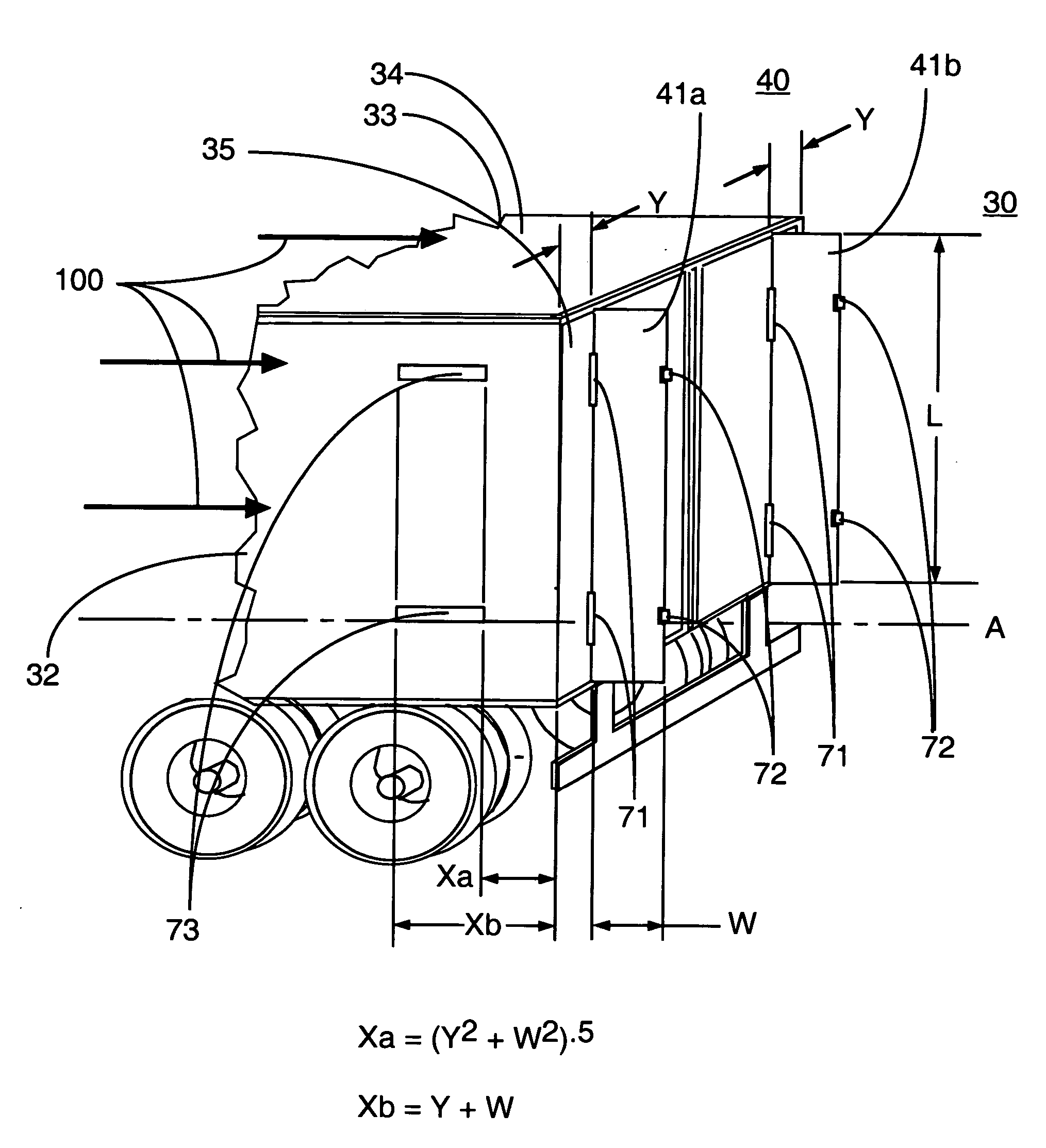
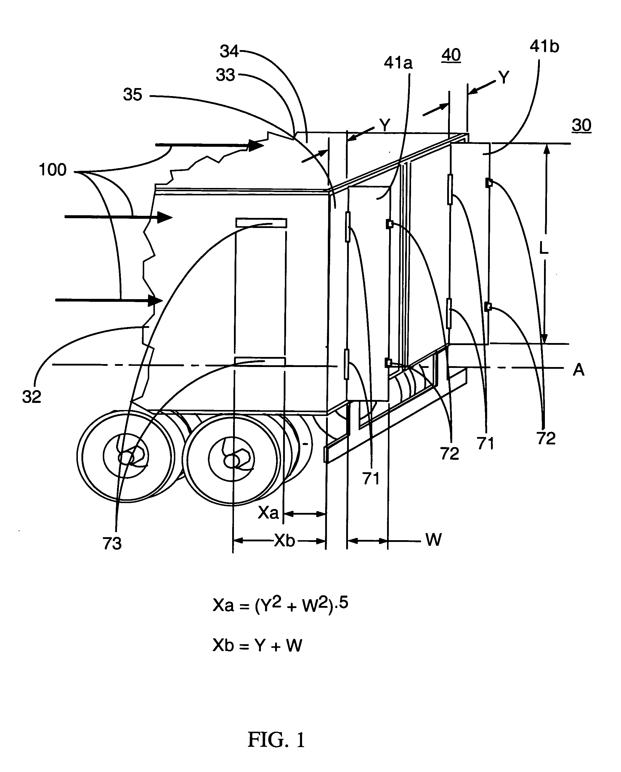
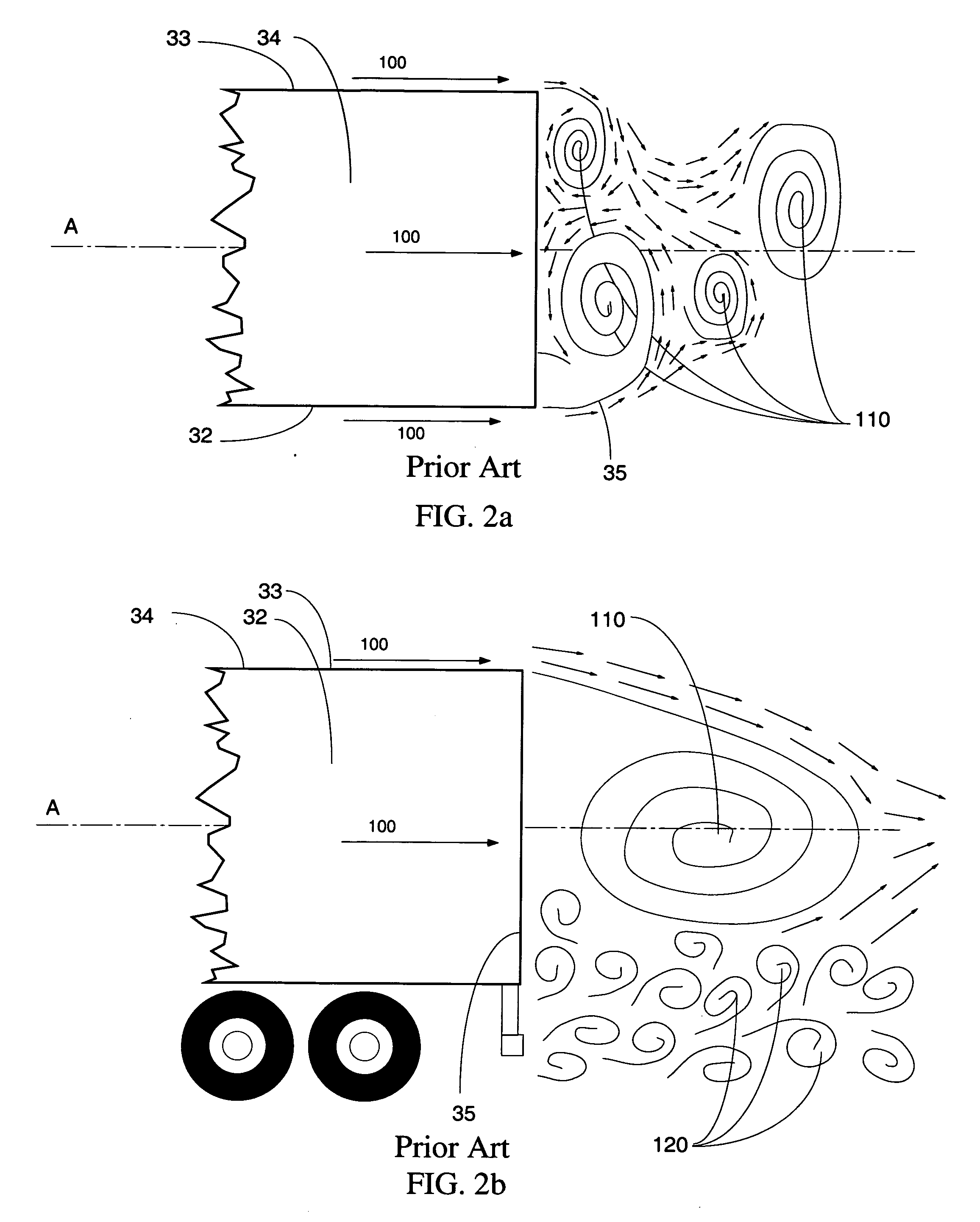
The wake flow emanating from the bluff base trailer is characterized as unsteady and dynamic.
The unsteady nature of the wake flow is a result of asymmetric and oscillatory vortex shedding of the side surface and top surface flow at the trailing edge of the top and side surfaces of the vehicle.
The low energy flow separating at the trailing edges of the side surfaces and top surface of the trailer is unable to energize and stabilize the low energy bluff-base wake flow.
The large rotational-flow structures comprising the wake interact with each other imparting an unsteady pressure loading on the vehicle base.
The resulting flow interaction in the vehicle wake and unsteady pressure loading on the vehicle base contributes to the low pressures acting on the vehicle base and therefore high drag force.
The unsteady wake flow imparts a low pressure onto the aft facing surface of the trailer base that results in significant aerodynamic drag.
These representative aerodynamic boat-tail fairing devices, while successful in eliminating flow separation, are complex devices that are typically comprised of moving parts that require maintenance and add weight to the vehicle.
These attributes have a negative impact on operational performance and interfere with normal operations of the vehicle.
These representative trailer base devices, while successful in reducing the drag due to base flow are complex devices that are typically comprised of moving parts that require maintenance and add weight to the vehicle.
All of these devices add significant weight to the vehicle.
These attributes have a negative impact on operational performance and interfere with normal operations of the vehicle.
These devices provide a drag reduction benefit but they require maintenance and interfere with normal operations of the trailers fitted with swinging doors.
These devices also add weight to the vehicle that would have a negative impact on operational performance of the vehicle.
This patent provides a drag reduction benefit but as with the other devices discussed previously this device is complex, comprised of moving parts, interfere with normal operations of the truck and add weight to the vehicle.
These characteristics of the device results in a negative impact on the vehicle operational performance.

Method used


Image

  • Wake stabilization device and method for reducing the aerodynamic drag of ground vehicles
  • Wake stabilization device and method for reducing the aerodynamic drag of ground vehicles
  • Wake stabilization device and method for reducing the aerodynamic drag of ground vehicles

Examples


Embodiment Construction

[0054] The following descriptions are of exemplary embodiments of the invention only, and are not intended to limit the scope, applicability or configuration of the invention in any way. Rather the following description is intended to provide a convenient illustration for implementing various embodiments of the invention. As will become apparent, various changes may be made in the function and arrangement of the elements described herein without departing from the spirit and scope of the invention. For example, though not specifically described, many shapes, widths, leading edge shapes, spacing and orientation of the forward extended plurality of panels, candidate vehicles that can benefit from the device, fabrication means and material, attachments means and material should be understood to fall within the scope of the present invention.

[0055] Referring now in detail to the drawings, like numerals herein designate like numbered parts in the figures.

[0056]FIG. 1 is a rear perspect...


PUM


Abstract

An improved method and device for the reduction of aerodynamic drag and for improved performance of bluff base vehicles by increasing the pressure on the bluff base of the vehicle by controlling the wake flow and the interaction of the wake flow with the vehicle bluff base region. An improved method and device for generating a reduction in drag force on the bluff base of a body moving through a fluid. The apparatus consists of two opposing panels attached to the bluff base and aligned approximately parallel to the side edge of the bluff base and lying in a plane that is parallel to the vehicle centerline. The drag force reduction results from controlling the flow entering the bluff base trailing wake from the left side surface, right side surface, bottom surface, and top surfaces of the vehicle. The objects and advantages also extend to other applications in which an object, body, or vehicle is moving through either a gas or a fluid.

Description

CROSS-REFERENCE TO RELATED APPLICATIONS [0001] This application claims a previous provisional patent application, No. 60 / 717,017 with a filing date of Sep. 15, 2005 and entitled “Wake stabilization device and method for reducing the aerodynamic drag of ground vehicles”.ORIGIN OF THE INVENTION [0002] The invention described herein was made by employees of the United States Government, and may be manufactured and used by or for the Government without payment of any royalties thereon or therefor. REFERENCE TO SEQUENCE LISTING, A TABLE, OR A COMPUTER PROGRAM LISTING COMPACT DISK APPENDIX [0003] Not applicable. BACKGROUND [0004] 1. Field of Invention [0005] The invention relates to the reduction of aerodynamic drag for moving ground vehicles; specifically to an improved method and device for the reduction of aerodynamic drag and for improved performance of ground vehicles by increasing the pressure on the base area of a vehicle or vehicle component by controlling the flow in wake of the ...

Claims


Application Information

Patent Timeline
Patent Type & Authority Applications(United States)
IPC IPC(8): G01F1/32
CPCB62D35/001
Inventor WOOD, RICHARD MICHAEL
Owner WOOD RICHARD MICHAEL
Learn More