Heat sink

Inactive Publication Date: 2007-04-26
HON HAI PRECISION IND CO LTD
View PDF4 Cites 18 Cited by
  • Summary
  • Abstract
  • Description
  • Claims
  • Application Information

AI Technical Summary

Benefits of technology

[0004] The present invention relates to a heat sink for dissipating heat from a heat-generating electronic component. According to a preferred embodiment of the present invention, the heat sink includes a plurality of fins. Each of the fins includes a main body and at least one bulge disposed on the main body. The main bodies of two adjacent fins coop

Problems solved by technology

The increase in thickness of the laminar sublayer

Method used


Image

  • Heat sink
  • Heat sink
  • Heat sink

Examples


Example

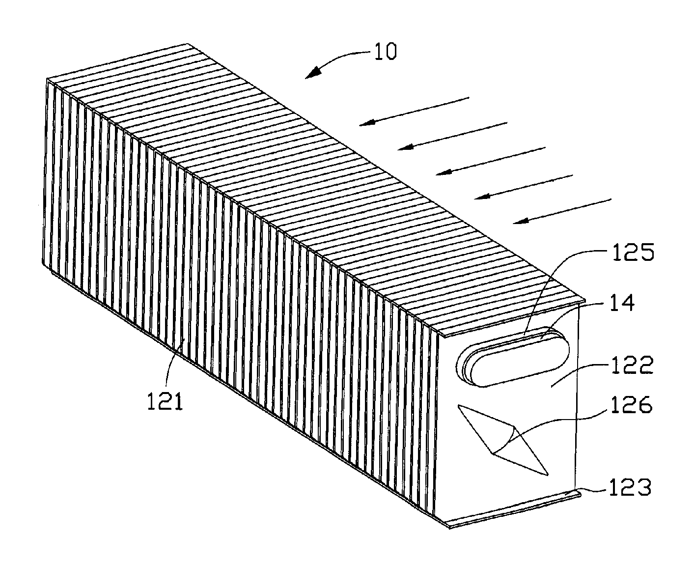
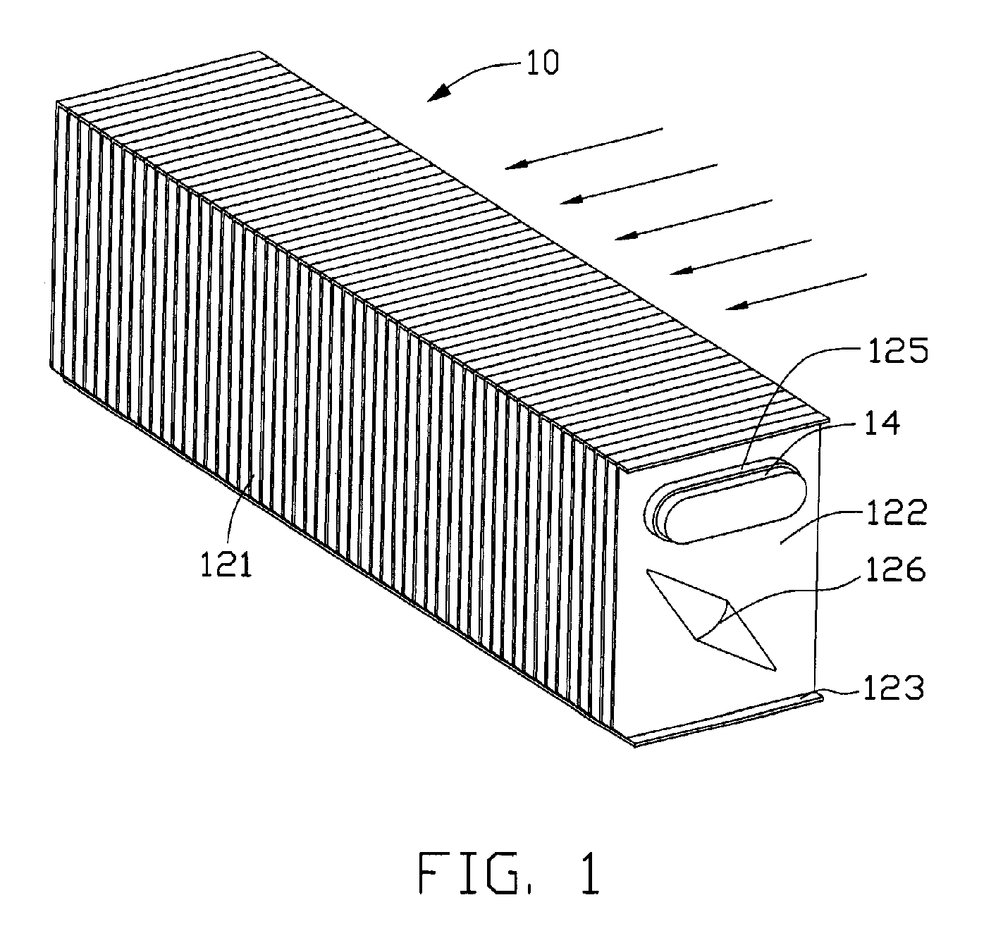
[0010] Referring to FIGS. 1 and 2, a heat sink 10 according to a preferred embodiment of the present invention is shown. A heat dissipating fan (not shown) is disposed at one side of the heat sink 10, for providing an airflow passing through the heat sink 10 to take away heat therefrom as indicated by arrows of FIG. 1. The heat sink 10 includes a plurality of parallel fins 12 and a heat pipe 14 extending through the fins 12. The heat pipe 14 has two opposite ends respectively connecting with a heat-generating electronic component (not shown) and the fins 12, for transferring heat therebetween.

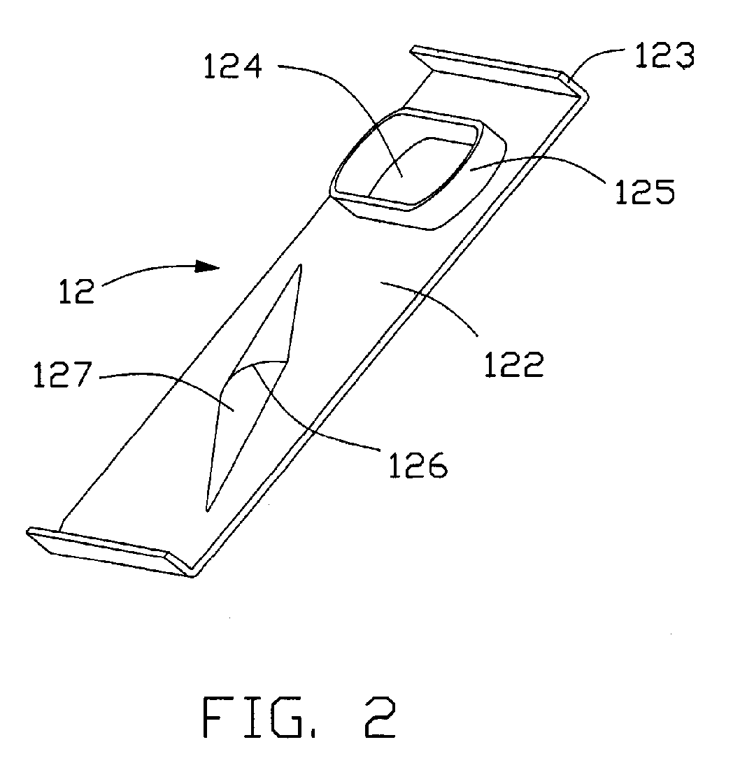
[0011] Each of the fins 12 includes a rectangular shaped main body 122, and two flanges 123 extending from two opposite ends of the main body 122. The fins 12 are stacked together with the flanges 123 of a rear fin 12 abutting against the main body 122 of a front fin 12. A plurality of air passages 121 are formed between two adjacent fins 12 to allow the airflow pass through. The main body 122...


PUM


Abstract

A heat sink (10) includes a plurality of fins (12). Each of the fins includes a main body (122) and at least one bulge (126) disposed on the main body. The main bodies of two adjacent fins cooperatively define an air passage (121) therebetween, for allowing an airflow to pass therethough. The bulge has a varying projection height so as to form a streamline guide surface (127) thereon.

Description

FIELD OF THE INVENTION [0001] The present invention relates generally to a heat sink, and more particularly to a heat sink for dissipating heat generated by electronic components, wherein fins of the heat sink project bulges therefrom for increasing heat dissipation efficiency of the heat sink. DESCRIPTION OF RELATED ART [0002] A conventional heat dissipating apparatus includes a heat sink thermally connected with a heat source for absorbing heat therefrom, and a heat dissipating fan for providing an airflow, which flows through the heat sink to take away heat therefrom. The heat sink includes a plurality of fins with two opposite planar surfaces. A plurality of air passages is formed between the fins allowing the airflow to flow therebetween. [0003] When the airflow flowing through the air passages of the heat sink, the airflow is laminar or turbulent. Turbulent airflow increases heat convection efficiency between the fins and the airflow, which further increases heat dissipation e...

Claims


Application Information

Patent Timeline
IPC IPC(8): F28D1/02
CPCF28D15/0266F28F1/24F28F13/06H01L23/3672H01L23/467H01L2924/0002F28D15/0275H01L2924/00F28D15/0233F28F2215/10
Inventor HWANG, CHING-BAIZHU, XI-JIAN
Owner HON HAI PRECISION IND CO LTD
Why Eureka
Try Eureka